Transcription of Proportional controls for PVPC pumps - Atos
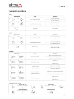
1 Proportional controls for pvpc pumps analog pressure or flow, digital P/Q controlsThe variable displacement axial pistonpumps type pvpc , can be supplied withadvanced electrohydraulic proportionalcontrols: open loop pressure control ; open loop flow control (load sensing); closed loop P/Q control ; They allow to perform high dynamics andfine regulations, directly commanded fromPLC or from the machine PES digital controllers, integrated tothe pump, performs alternate closed loopcontrols of pressure, flow and max powerlimitation. It is also available with optionalsequence module (PERS versions) thatallows to reduce close to zero thepressure to the delivery J744 mounting flange and displacement: 29, 46, 73, 88 cm3/revMax pressure: 280 bar working350 bar peakFor technical characteristics and features,see tech table CODE1AS170 pvpc ---4*X2 EPERS - SPBC*1D//10046 Type of control (see section7and 8):CZ = Proportional pressure controlLQZ = prop.
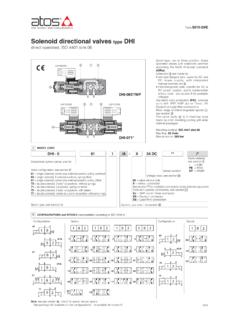
2 Flow control (load sensing)PES-SP = closed loop integral digital P/Q driverPERS-SP = as PES plus sequence moduleSize:3= for displacement 029 4= for displacement 046 5= for displacement 073 and 090 Max displacement:029= 29 cm3/rev 046= 46 cm3/rev 073= 73 cm3/rev 090= 88 cm3/revType of PFE (for double pumps ), see tech table A005 Shaft (SAE Standard):1 = keyed (7/8 for 029 - 1 for 0461 1/4 for 073 and 090)5 = splined (13 teeth for 029 - 15 for 04614 for 073 and 090)Direction of rotation (viewed at the shaft end)D = clockwise S = counterclockwiseVariable displacementaxial piston pumpAdditional suffix for double pumpsX2E = with a fixed displacementpump type PFE(see tech table A005)**Series numberPressure setting (only for PERS): 200= 200 bar 250= 250 bar 280= 280 barOptions, for CZ, LQZ see sections4:18 =optional coil for low currentdriversElectronics options for PES andPERSsee section:C=current feedback for pressuretransducer 4 20 mAI =current reference input and monitor4 20 mA (omit for standard voltagereference input and monitor 10 V)X=with integral pressure transducer(only for PERS)S=with two on-off inputs for multiplepressure PID selection (NPexecution) or double power supply(BC, BP, EH, EW and EP execution).
3 11 Seals material: = NBRPE= FKMF ieldbus interfacesfor PES and PERS:USB interface always presentNP = Not present BC = CANopen EH = EtherCATBP = PROFIBUS DP EI = EtherNet/IPEW= POWERLINK EP = PROFINET IRT pump body Proportional valve integral electronics with P/Q controller USB connector swash plates transducer connection fieldbus connector main connector remote pressure transducer///Table AS170-2/EPump model pvpc -*-3029 pvpc -*-4046 pvpc -*-5073 pvpc -*-5090 Displacement [cm3/rev] 29 46 73 88 Theorical max flow at 1450 rpm [l/min] 42 66,7 105,8 127,6 Max working pressure / Peak pressure [bar] 280/350 280/350 280/350 250/315 Min/Max inlet pressure [bar abs.]
4 ] 0,8 / 25 0,8 / 25 0,8 / 25 0,8 / 25 Max pressure on drain port [bar abs.] 1,5 1,5 1,5 1,5 19,9 31,6 50,1 54,1 Max torque on the first shaft [Nm] Speed rating [rpm]Type1200 Type5190 Power consumption at 1450 rpm andat maximum pressure and displacementMax permissible load ondrive shaft2 OPERATING CHARACTERISTICSType1230 Type5330 Type1490 Type5620 Type1490 Type5620500 3000[kW]FaxFrad[N]10001500500 260015001500500 260020003000500 220020003000 Notes: For speeds over 1800 rpm the inlet port must beunder oil level with adequate pressure for all models with water glycol fluid is160 bar, with /PE options is 190 speed with /PE options and water glycol fluid is2000/1900/1600/1500 rpm respectively for the four =axial loadFrad =radial loadExternal load positionAtos Proportional pumps are CE marked according to the applicable Directives ( Immunity/Emission EMC Directive and Low VoltageDirective).
5 Installation, wirings and start-up procedures must be performed according to the general prescriptions shown in table F003 and in the installa-tion notes supplied with relevant electrical signals of the pump ( monitor signals) must not be directly used to activate safety functions, like to switch-ON/OFF the machi-ne s safety components, as prescribed by the European standards (Safety requirements of fluid technology systems and components-hydrau-lics, EN-982).3 GENERAL NOTES4 MAIN CHARACTERISTICS - based on mineral oil ISO VG 46 at 50 C Assembly position Any position. The drain port must be on the top of the pump. Drain line must be separated andunrestricted to the reservoir and extended below the oil level as far from the inlet as maximum line lenght is 3 m. Subplate surface finishing Roughness index, Ra 0,4 flatness ratio 0,01/100 (ISO 1101) -CZ, -LQZ execution = -20 C +70 C Ambient temperature range -PES and -PERS executions = -20 C +60 CStorage temperature range -20 C +70 C Coil resistance R at 20 C pump size 3 3 3,3 for standard 12 VDCcoil; 13 13,4 for 18 VDCcoil (only for version CZ, LQZ) pump size 4, 5 3,8 4,1 for standard 12 VDCcoil; 12 12,5 for 18 VDCcoil (only for version CZ, LQZ) Max.
6 Solenoid current 2,6 A for standard 12 VDCcoil; 1,5 A for standard 18 VDCcoil (only for version CZ, LQZ) Max. power CZ, LQZ execution = 35 Watt; PES, PERS executions = 50 Watt Power supply for pressure transducer (PE*S) 24 VDC Insulation class H (180 ) Due to the occuring surface temperatures of the solenoid coils, the European standards ISO 13732-1 and EN982 must be taken into account Protection degree to DIN EN60529 CZ, LQZ executions = IP65 PES, PERS executions = IP66/67 with mating connector Duty factor Continuous rating (ED=100%) EMC, climate and mechanical load See technical table G004 Mineral oilsHydraulic fluidNBR, FKMFKMNBRDIN 51524 ISO 12922HL, HLP, HLPD, HVLP, HVLPDHFDU, HFDRHFCS uitable seals typeClassificationRef.
7 StandardFlame resistant without waterFlame resistant with water5 SEALS AND HYDRAULIC FLUID - for other fluids not included in above table, consult our technical officeNote:for other fluids not included in above table, consult our technical office NBR seals = -20 C +60 C, with HFC hydraulic fluids = -20 C +50 C Seals, recommended temperature fluid FKM seals = -20 C +80 C Recommended viscosity 20 100 mm2/s - max allowed range 15 380 mm2/s - max start-up viscosity 1000 mm2/s Fluid contamination class ISO 4406 class 20/18/15 NAS 1638 class 9, in line filters of 10 m ( 10 _>75 recommended)OPEN LOOP ELECTROHYDRAULIC CONTROLS7 Pressure [bar]CZProportional pressure controlOpen loop control of the pump max pressureThe pumps displacement, and thus the flow,remains constant as far the pressure in the circuitreaches the value set on the Proportional pilot valve , then the flow is reduced to maintain the circuitpressure to the value set by the electronic referen-ce signal to the Proportional valve.
8 In this condi-tions the pressure in the circuit can be continuoslymodulated by means of the reference pressure setting range: see belowpressure control setting range : 20 350 bar(315 bar for 090)Compensator factory setting : 280 bar(250 bar for 090)Flow [l/min]Hysteresis and pressureincrease: max 4 barProportional flow (load-sensing)Open loop control of the pump flow independentto the cyrcuit load. The pump displacement isself adjusted to maintain a costant pressure dropacross the Proportional flow control valve .The pump flow can be continuosly regulated bymodulating the Proportional valve .LQZP ressure [bar]Flow [l/min]Regulation diagrams1 = Flow control2 = Pressure control (1) for standard 12 VDC coil(2) for 18 VDC coilDiagrams for CZ, LQZ12 Regulated flow [l/ min]Driving current [mA](1)(2)Regulated pressure [bar]Driving current [mA](1)(2) Pump size 88 73 46 29 cm3/rev AS170 6 ELECTRONIC DRIVERSNote:for power supply and communication connector see table GS2158 CONNECTIONS FOR CZ AND LQZ Signal description SUPPLY SUPPLY GNDPIN123 SOLENOID POWER SUPPLY CONNECTOR123 Pump modelCZ, LQZPES, PERSD rivers modelE-MI-AC-01FE-BM-ACE-ME-ACE-MI-AS-IR E-BM-AS-PSE-BM-AESE-RI-PESTypeAnalogDigi talFormatplug-into solenoidDIN 43700 UNDECALEUROCARD plug-into solenoidDIN-rail panelIntegral to valveData sheetG010G025G035G020G030GS050GS2159P/Q digital CONTROLLERPESPERSPERS/XDisplacement [%]Regulated flow [l/min]Reference [%]Operating pressure [bar]FeedbackReference12 Pressure transducerincluded only forPERS/XPressure transducer not includedTime [ms]Displacement [%]Response timeRegulated flowP/Q controlPVPC-PE(R)S-3029 pvpc -PE(R)S-4046 pvpc -PE(R)S-5073 pvpc -PE(R)
9 S-50903040506060801001209012015017030405 0606080100120 Type pumpd1d2d3[ms]d4d5 Response time of displacement variation for a step change of the electronic reference PRESSURE TRANSDUCER SELECTIONThe pressure transducer type E-ATR-8 must be ordered separately (see tech tableGS465)For /X option the pressure transducer with output signal 4 20 mA is integral to the code: pvpc -PER(S)-*/200 pvpc -PER(S)-*/250 pvpc -PER(S)-*/280 pvpc -PER(S)-*/200/*/CPVPC-PER(S)-*/250/* /CPVPC-PER(S)-*/280/*/CPressure transducer code:E-ATR-8/250E-ATR-8/400E-ATR-8/400E- ATR-8/250/IE-ATR-8/400/IE-ATR-8/400/IDig ital P/Q controller integrates the alternate pressure and flow regulation withthe electronic max power remote pressure transducer must be installed on the system and its feedbackhas to be interfaced to the pump digital driver. Flow control is active when the actual system pressure is lower than the pressurereference input signal: the pump flow is regulated according to the flow reference control is activated when the actual pressure grows up to the pressurereference input signal: the pump flow is then reduced in order to regulate andlimit the max system pressure (if the pressure tends to decrease under its com-mand value, the flow control returns active).
10 This option allows to realize accura-te dynamic pressure profiles. Following fieldbus interfaces are available: BC - CANopen interface BP - PROFIBUS DP interface EH - EtherCAT interface EW- POWRELINK interface EI - EtherNet/IP interface EP - PROFINET IRT interfaceThe pumps with BC, BP, EH, EW, EI and EP interfaces can be integrated into afieldbus communication network and thus digitally operated by the machinecontrol digital control ensures high performances as flow and pressure linearity(see diagram 1), better flow knee (see diagram 2), internal leakage compensa-tion (controlled flow independent to the load variations). pvpc -PES basic version, without sequence module and without pressuretransducer, which has to be installed on the main line and wiredto the 12 poles connector of the integral digital version with sequence module RESC which grant a minimumpiloting pressure (18 bar) when the actual pressure falls belowthat value. Without pressure as PERS version plus integral pressure transducer, with outputsignal 4 20 mA, factory wired to the pump digital electronicsthrough a cable option/X and /SX options = remote transducer = M12 connectorNote: and to be ordered separately = remote transducer = main connectorNote: and to be ordered separately = integral transducer = M12 connectorNote: and included L1 L2 L3 AEEE12 CONNECTIONS AND LEDSMAIN CONNECTORUSB CONNECTOR(always present)Note:connectors front viewFIELDBUSCONNECTORUSB(female)EtherCAT , POWERLINK,EtherNet/IP - PROFINET IRT(female - INPUT)CANopen(male)12 PIN MAIN CONNECTOR(male)CANopen(female)PROFIBUS DP(male)PROFIBUS DP(female)FIELDBUSCONNECTORPEDIAGNOSTIC LEDSINTEGRAL SWASHPLATETRANSDUCERREMOTE PRESSURETRANSDUCER/X option(female)PRESSURETRANSDUCER(only for /X option)Standard execution provides on the 12 pin main connector.