Transcription of Proportional controls for PVPC pumps - atos.com
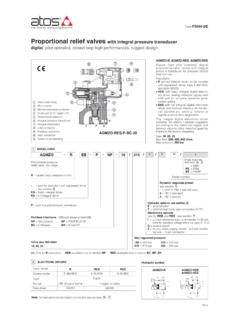
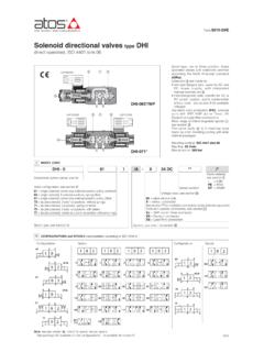
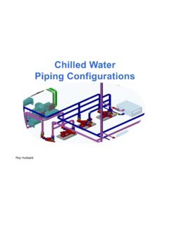
1 Proportional controls for axial piston pumps pressure, flow or P/Q controlsPVPC-PES-SP-BC-4046 MODEL CODE1AS170 PVPC---*X2 EPERS-SPBC*1D//*4046 Type of control, see section and : CZ = Proportional pressure control (1) LQZ = Proportional flow control (load sensing) (1) PES-SP = closed loop integral digital P/Q driver PERS-SP = as PES plus sequence module1011 Direction of rotation, viewed at the shaft end: D = clockwise S = counterclockwiseVariable displacement axial piston pump*Series numberPressure setting, only for PERS: 200 = 200 bar 250 = 250 bar 280 = 280 barCoil voltage, for CZ, LQZ - see section : 18 = optional coil for low current drivers Electronics options, for PES and PERS (4): C= current feedback for pressure transducer 4 20 mA (omit for std voltage 10 VDC) I = current reference input and monitor 4 20 mA (omit for std voltage 10 VDC) X= on-board pressure transducer with pre-configured pressure settings (only for PERS) S= with 2 on-off inputs for multiple pressure PID selection for NP execution or double power supply for fieldbus execution, plus dedicated connector for remote pressure transducer 15 Pump body Proportional valve On-board driver with P/Q control USB connector Swash plates transducer connection Fieldbus connector Main connector Remote pressure transducer// Size and max displacement (3).
2 3029 = size 3 - displacement 029 cm3/rev 4046 = size 4 - displacement 046 cm3/rev 5073 = size 5 - displacement 073 cm3/rev 5090 = size 5 - displacement 090 cm3/rev 6140 = size 6 - displacement 140 cm3/rev(1) Not available for PVPC-*-6140 (2) Only for PES and PERS (3) Optional intermediate displacements 35 and 53 cm3/rev are available on request (4) For possible combined options, see section (5) pumps with ISO 3019/2 mounting flange and shaft (option /M) are available on request14 PVPC Variable displacement axial piston pumps with swash plate design suited for high pressure open circuits, they are provided with advanced electrohydraulic proportio-nal controls : CZ open loop pressure control LQZ open loop flow control (load sensing) PES closed loop P/Q control PES performs alternate closed loop controls of pressure, flow and max power limitation. It is also available with optional sequence module (PERS versions) that allows to reduce close to zero the pressure to the delivery line.
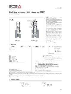
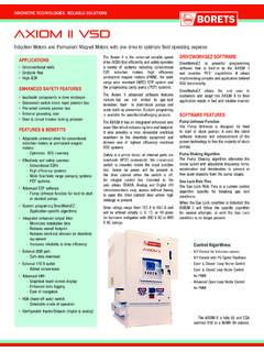
3 SAE J744 mounting flange and shaft. Max displacement (cm3/rev)Max pressure working (bar)Max pressure peak (bar)29, 46, 73, 140 88280 250 350 315 For technical characteristics and features, see tech table A160. Option for pumps with through shaft (1): XA = intermediate flange SAE A XB = intermediate flange SAE B XC = intermediate flange SAE C (only for size 5073 and 5090) Additional suffix for double pumps : X2E = with a fixed displacement pump type PFE (see tech table A005)Fieldbus interfaces, USB port always present (2): NP = Not present BC= CANopen EW = POWERLINK BP = PROFIBUS DP EI = EtherNet/IP EH = EtherCAT EP = PROFINET RT/IRTS haft, SAE Standard (5): 1 = keyed 5 = splined Seals material, see section : - = NBR PE = FKM 9 Table AS170-4/E3 GENERAL NOTESAtos digital proportionals pumps are CE marked according to the applicable directives ( Immunity and Emission EMC Directive). Installation, wirings and start-up procedures must be performed according to the general prescriptions shown in tech table FS900 and in the user manuals included in the E-SW-* programming software.
4 Fieldbus allows valve direct communication with machine control unit for digital reference, valve diagnostics and settings. These execution allow to operate the valves through fieldbus or analog signals available on the main connector. 5 FIELDBUS - see tech. table GS5104 PUMP SETTINGS AND PROGRAMMING TOOLSPump's functional parameters and configurations, can be easily set and optimized using Atos E-SW programming software connected via USB port to the digital driver (see table FS900). For fieldbus versions, the software permits pump s parameterization through USB port also if the driver is connected to the central machine unit via or Bluetooth connectionE-C-SB-USB/M12 cableE-A-SB-USB/OPT isolatorThe software is available in different versions according to the driver s options (see table GS500): E-SW-BASIC support: NP (USB) PS (Serial) IR (Infrared) E-SW-FIELDBUS support: BC (CANopen) BP (PROFIBUS DP) EH (EtherCAT) EW (POWERLINK) EI (EtherNet/IP) EP (PROFINET) E-SW-*/PQ support: valves with SP, SF, SL alternated control ( E-SW-BASIC/PQ)WARNING: drivers USB port is not isolated!
5 For E-C-SB-USB/M12 cable, the use of isolator adapter is highly recommended for PC protectionE-C-SB-M12/BTH cableE-A-SB-USB/BTH adapterWARNING: see tech table GS500 for the list of countries where the Bluetooth adapter has been approved6 GENERAL CHARACTERISTICS2 OFF-BOARD ELECTRONIC DRIVERS - only for CZ, LQZD rivers modelE-MI-AC-01FE-MI-AS-IRE-BM-AS-PSE-BM -AESTypeAnalogDigitalVoltage supply (VDC)12241224122424 Valve coil option/6std/6std/6stdstdFormatplug-in to solenoidDIN-rail panelData sheetG010G020G030GS050 Assembly positionAny position. The drain port must be on the top of the pump. Drain line must be separated and unrestricted to the reservoir and extended below the oil level as far from the inlet as possible. Suggested maximum line lenght is 3 surface finishing to ISO 4401 Acceptable roughness index: Ra 0,8, recommended Ra 0,4 Flatness ratio 0,01/100 MTTFd valves according to EN ISO 13849150 years, see technical table P007 Ambient temperature rangeCZ,LQZ: Standard = -25 C +60 C /PE option = -15 C +80 C PES, PERS: Standard = -20 C +60 C /PE option = -20 C +60 CStorage temperature rangeCZ,LQZ: Standard = -20 C +80 C /PE option = -20 C +80 C PES, PERS: Standard = -20 C +70 C /PE option = -20 C +70 CSurface protection (pump body)Black painting RAL 9005 Surface protection (pilot valve)Zinc coating with black passivation, galvanic treatment (driver housing for AEB and AES)Corrosion resistance (pilot valve)Salt spray test (EN ISO 9227) > 200 hCompliance ( Proportional pilot valve)CE according to EMC directive 2014/30/EU (Immunity: EN 61000-6-2.)
6 Emission: EN 61000-6-3) RoHS Directive 2011/65/EU as last update by 2015/65/EU REACH Regulation (EC) n 1907/2006 PVPC size30294046507350906140 Max displacement29467388140 Theoretical max flow at 1450 rpm4266,7105,8127,6203 Max working pressure / Peak280/350280/350280/350250/315280/350 (1)Min/Max inlet pressure0,8 / 250,8 / 250,8 / 250,8 / 250,8 / 25 Max pressure on drain port1,51,51,51,51,5 Power consumption at 1450 rpm and at max pressure and displacement19,931,650,154,1122 Max torque on the first shaftType 1 210 Type 5 270 Type 1 350 Type 5 440 Type 1 670 Type 5 810 Type 1 670 Type 5 810 Type 1 1000 Type 5 2340 Max torque at max working pressure128203328350780 Speed rating500 3000500 2600500 2600500 2200500 2200 Body volume0,70,91,51,52,87 HYDRAULIC CHARACTERISTICS - based on mineral oil ISO VG 46 at 50 C(cm3/rev) (l/min) (bar) (bar abs.) (bar abs.) (Kw) (Nm) (Nm) (rpm) (l)Notes: For speeds over 1800 rpm the inlet port must be under oil level with adequate pipes.
7 Maximum pressure for all models with water glycol fluid is 160 bar, with /PE options is 190 bar. Max speed with /PE options and water glycol fluid is 2000/1900/1600/1500 rpm respectively for the four = axial load Frad= radial loadExternal load position8 ELECTRICAL CHARACTERISTICSNote: a maximum time of 800 ms (depending on communication type) have be considered between the driver energizing with the 24 VDC power supply and when the valve is ready to operate. During this time the current to the valve coils is switched to supplies Nominal : +24 VDC Rectified and filtered : VRMS = 20 32 VMAX (ripple max 10 % VPP)Max power consumptionCZ, LQZ = 35 Watt; PES, PERS = 50 WattMax. solenoid current2,6 A for standard 12 VDC coil; 1,5 A for standard 18 VDC coil (only for CZ, LQZ)Coil resistance R at 20 CSize 3: 3 3,3 for standard 12 VDC coil; 13 13,4 for 18 VDC coil (only for version CZ, LQZ)Size 4, 5: 3,8 4,1 for standard 12 VDC coil; 12 12,5 for 18 VDC coil (only for version CZ, LQZ)Analog input signalsVoltage: range 10 VDC (24 VMAX tollerant)Input impedance: Ri > 50 k Current: range 20 mA Input impedance: Ri = 500 Monitor outputsOutput range: voltage 10 VDC @ max 5 mA current 20 mA @ max 500 load resistance Enable inputRange: 0 5 VDC (OFF state), 9 24 VDC (ON state), 5 9 VDC (not accepted); Input impedance: Ri > 10 k Fault outputOutput range: 0 24 VDC (ON state > [power supply - 2 V] ; OFF state < 1 V ) @ max 50 mA.
8 External negative voltage not allowed ( due to inductive loads)Pressure transducer power supply+24 VDC @ max 100 mA (E-ATR-8 see tech table GS465)AlarmsSolenoid not connected/short circuit, cable break with current reference signal, over/under temperature, valve spool transducer malfunctions, alarms history storage functionInsulation classH (180 ) Due to the occuring surface temperatures of the solenoid coils, the European standards ISO 13732-1 and EN982 must be taken into accountProtection degree to DIN EN60529CZ, LQZ = IP65; PES, PERS = IP66/67 with mating connectorDuty factorContinuous rating (ED=100%)TropicalizationTropical coating on electronics PCBA dditional characteristicsShort circuit protection of solenoid s current supply; 3 leds for diagnostic; spool position control by with rapid solenoid switching; protection against reverse polarity of power supplyCommunication interfaceUSB Atos ASCII codingCANopen EN50325-4 + DS408 PROFIBUS DP EN50170-2/IEC61158 EtherCAT, POWERLINK, EtherNet/IP, PROFINET IO RT / IRT EC 61158 Communication physical layernot insulated USB + USB OTGoptical insulated CAN ISO11898 optical insulated RS485 Fast Ethernet, insulated 100 Base TX Recommended wiring cableLiYCY shielded cables, see section 20AS170(1) The maximum pressure can be increased to 350 bar (working) and 420 (peak) after detailed analysis of the application and of the pump working cycle9 SEALS AND HYDRAULIC FLUIDS - for other fluids not included in below table, consult our technical office Seals, recommended fluid temperatureNBR seals (standard) = -20 C +60 C, with HFC hydraulic fluids = -20 C +50 C FKM seals (/PE option) = -20 C +80 C Recommended viscosity20 100 mm2/s - max allowed range 15 380 mm2/s Hydraulic fluidSuitable seals typeClassificationRef.
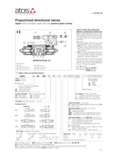
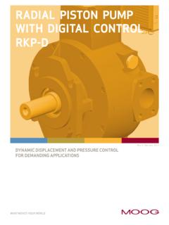
9 Standard Mineral oilsNBR, FKM, HNBRHL, HLP, HLPD, HVLP, HVLPDDIN 51524 Flame resistant without waterFKMHFDU, HFDR (1) ISO 12922 Flame resistant with waterNBR, HNBRHFC (1)Max fluid contamination level see also filter section at or KTF catalognormal operation longer lifeISO4406 class 18/16/13 NAS1638 class 7 ISO4406 class 16/14/11 NAS1638 class 5 OPEN LOOP ELECTROHYDRAULIC CONTROLS10 Pressure [bar]CZProportional pressure control Open loop control of the pump max pressure The pumps displacement, and thus the flow, remains constant as far the pressure in the circuit reaches the value set on the Proportional pilot valve , then the flow is reduced to maintain the circuit pressure to the value set by the electronic referen-ce signal to the Proportional valve. In this condi-tions the pressure in the circuit can be continuosly modulated by means of the reference signal. Proportional pressure setting range: see below pressure control diagram. Compensator setting range : 20 350 bar (315 bar for 090) Compensator factory setting : 280 bar (250 bar for 090)Flow [l/min]Hysteresis and pressure increase: max 4 barProportional flow (load-sensing) Open loop control of the pump flow independent to the cyrcuit load.
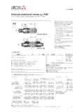
10 The pump displacement is self adjusted to maintain a costant pressure drop across the Proportional flow control valve . The pump flow can be continuosly regulated by modulating the Proportional valve .LQZP ressure [bar]Flow [l/min]Regulation diagrams 1 = Flow control 2 = Pressure control (1) for standard 12 VDC coil (2) for 18 VDC coilDiagrams for CZ, LQZ12 Regulated flow [l/ min]Driving current [mA](1)(2)Regulated pressure [bar]Driving current [mA](1)(2) Pump size 88 73 46 29 cm3/rev (1) Max working pressure must be reduced to: 180 bar (working) / 210 bar (peak) for HFC fluid 200 bar (working) / 240 bar (peak) for HFDU and HFDR fluidAS17011P/Q CONTROLPESPERS PERS/XDisplacement [%]Regulated flow [l/min]Reference [%]Operating pressure [bar]FeedbackReference12 Pressure transdu-cer included only for PERS/XPressure transducer not includedTime [ms]Displacement [%]Response timeRegulated flowP/Q controlResponse time of displacement variation for a step change of the electronic reference TRANSDUCER SELECTIONThe pressure transducer type E-ATR-8 must be ordered separately (see tech table GS465) For /X option the pressure transducer with output signal 4 20 mA is on-board to the pump.