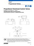
Transcription of Proportional Direction Valves without Feedback - Eaton
1 Proportional Direction Valves without Feedback Pressures to 315 bar (4500 psi). KBD/TG4V-5, 1* Series Contents General Description 3. Typical Section 3. Model Codes 4. Spool Data 5. Functional Symbols 5. Operating Data 6. Power Capacity Envelopes 8. Frequecy Response 8. Flow Characteristics 9. Installation Dimensions KBDG4V-5 11. KBTG4V-5 11. Mounting Surface Interface to ISO 4401 (Size 05) 12. Electrical Information Block Diagram 13. Typical Connection Arrangements 14. Application Data 15. 2 Eaton Vickers Proportional directional Valves without Feedback KBD/TG4V-5 V-VLDI-MC002-E September 2004. Introduction General Description Electrical connection is via a New Features and Standard Features and standard 7-pin plug and Benefits Benefits Vickers KB*G4V-5 propor- TM. requires a power supply and tional Valves are designed to command signal which can State of the art digital Factory adjusted to ensure provide controlled oil flow in be either voltage or current electronic technology excellent valve-tovalve proportion to an electrical (model code option).
2 Reproducibility Rugged and robust die- command signal. They are In addition to improving cast housing Installation wiring reduced available in two versions. machine performance and Optional voltage (+/-10 and simplified Firstly a double solenoid version that will provide life, the KB Proportional volt) or current (4-20 mA) Wide range of spool and reversible flow and return to Valves substantially simplify demand input flow rate options an actuator. Secondly a sin- system design by combining Adjustable ramp (2 sec) Simple valve removal and gle solenoid version that Direction and flow capabili- Wide range of supply replacement for service provides a single Direction ties in one single package voltage plug and play of flow. that mounts onto a standard ISO 4401 interface. Optional external enable Standard 7-pin connector The KB valve incorporates an integral control amplifier. feature 315 bar (4500 psi). Factory set adjustments for IP67 environmental pressure rating gain, spool deadband com- protection Supported by auxiliary pensation and dither ensure Full CE electromagnetic function electronic excellent reproducibility capability to EN 50081-2 modules valve-to-valve.
3 And EN 50082-2. Vibration and shock tested Typical Section KBDG4V-5-PE, 1* Series Eaton Vickers Proportional directional Valves without Feedback KBD/TG4V-5 V-VLDI-MC002-E September 2004 3. Model Code KB * G 4 V 5 ** * ** * ** * M * P*7 H 7 10. 1 2 3 4 5 6 7 8 9 10 11 12 13 14 15 16 17. 1 Valve type 8 Spool/Spring 12 Manual Overrides WARNING. KB Proportional valve with Arrangement Z No overrides Valves with integral (See next page for amplifiers are sup- integral amplifier, B. series Spool Configurations) 13 Electrical Command plied with or without the C Spring centered, dual Option metal 7-pin plug. The Vickers 2 Control Type solenoid plug, part no. 934939, must 1 +/- 10V control signal D directional valve be correctly fitted to ensure B Spring centered, single 2 4-20 mA control signal solenoid that the EMC rating and T Throttle valve IP67 rating are achieved. The 14 Electrical Connection 9 plug retaining nut must be 3 Mounting Spool Flow Rating - at PC7 7 pin connector without tightened with a torque of 2- 5 bar (75 psi) per meter G Subplate mounted plug supplied 2,5 Nm ( lbf ft) to ing flow path effect a proper seal.
4 30 30 L/min ( USgpm) PE7 7 pin connector with 4 Operation plug supplied 4 Solenoid operated 50 50 L/min ( USgpm). PH7 As PE7 but with pin 65 65 L/min ( USgpm) C used for enable 5 Pressure rating 70 70 L/min ( USgpm) signal V 315 bar (4500 psi), PR7 As PC7 but with pin ports P, A & B 10 Spool Metering Type C used for enable S Meter-out only signal 6 Interface (65 spool only). 15 Coil Rating 5 ISO 4401, size 05-02-0-94, N Meter-in and meter-out ANSI H 24V DC amplifier supply 11 Flow Rating for 7 Spool Type 16. Asymmetric Flow Spools T Port Pressure 2 Closed center (Omit for symmetrical spools) 6 160 bar (2270 psi) (65S. 33 P port closed, A & B spool only). 25 25 L/min ( USgpm). to tank 7 210 bar (3000 psi) (not (2C50N25 only). available with 65S spool). 35 35 L/min ( USgpm). 17 Design number 1 1* series - Subject to change 4 Eaton Vickers Proportional directional Valves without Feedback KBD/TG4V-5 May 2004. Spool Data Spool Symbols Available Spools for Spool Type and Flow Ratings KBDG4V-5 Symmetric Spools Spool code Spool symbol Flow rating Base line starting at p = 5 For KBDG4V-5 Valves : bar (72 psi) per metering 2C30N 2C 30 L/min ( USgpm).
5 Flow path, B to T. For 2C50N 2C 50 L/min ( USgpm). 2C70N 2C 70 L/min ( USgpm). actual maximum flow refer 2C65S 2C 65 L/min ( USgpm). Spool type 2C to power capacity envelope 33C30N 33C 30 L/min ( USgpm). curves. 33C50N 33C 50 L/min ( USgpm). For KBTG4V-5 Valves : 2B30N 2B 30 L/min ( USgpm). 2B50N 2B 50 L/min ( USgpm). Spool type 33C 2B70N 2B 70 L/min ( USgpm). Available Spools for Asymmetric Spools Spool code Spool symbol Flow rating KBTG4V-5 Figure preceding metering For KBDG4V-5 Valves : type designator, "N" ( 2C50N25 2C 50 L/min ( USgpm) A port flow 2C**N) is flow rating P-A, 25 L/min ( USgpm) B port flow 2C60N35 2C 60 L/min ( USgpm) A port flow or A-T ("A" port flow); figure 35 L/min ( USgpm) B port flow after "N" (N**) is flow rating 33C50N25 33C 50 L/min ( USgpm) A port flow P-B, or B-T ("B" port flow). 25 L/min ( USgpm). Spool type 2B P T B B A port flow L. meter-in/meter-out . Spool type 33B Functional Symbols meter-in/meter-out P T B A L P T B A L.
6 Model Type KBDG4V-5 Model Type KBTG4V-5. Proportional directional valve (with integrated electronics) Proportional throttle valve (with integrated electronics). s If port T pressure will not exceed 160 bar (2320 psi), port L need not to be connected to tank. Eaton Vickers Proportional directional Valves without Feedback KBD/TG4V-5 V-VLDI-MC002-E September 2004 5. Operating Data Proportional directional Valves without Feedback KBD/TG4V-5. Data is typical with fluid at 36 cSt (168 SUS) and 50 C (122 F). Power supply 24V DC (21V to 34V including 10% peak-to-peak ripple) max current Command signal (Volts) 0 to +10V DC, or 0 to 10V DC, or 10 V to +10 V DC. Input impedance 47 k . Common mode voltage to pin B 4V. Command signal (Current) 4 to 20 mA. Input impedance 100 . Valve enable signal Enable > (34V max). Disable < Input impedance 36 k . 7-pin plug connector A G Pin Description A Power supply positive (+). F B B Power 0V. C Valve enable (PH7 & PR7). D Command signal (+V or current in).
7 View of pins of fixed half E Command signal ( V or current return). E C. F Output monitor G Protective ground D. Electromagnetic compatibility (EMC): Emission (10 V/m) EN 50081-2. Immunity (10 V/m) EN 50082-2. Monitor signal (pin F) KDB values 2V for solinoid current Output impedance 10k . Power stage PWM frequency kHz nominal Step input response, with flow through P A B T, p=5 bar (72 psi) per metering path, P A. Required flow step for 24V version: Time to reach 90% of required step: 0 to 100% 115 ms 100% to 0 105 ms Reproducibility, valve-to-valve (at factory settings): 5%. Flow at 100% command signal Protection: Electrical Reverse polarity protected Environmental IEC 529, Class IP67. Ambient air temperature range for full performance 0 C to 70 C (32 F to 158 F). Oil temperature range for full performance 0 C to 70 C (32 F to 158 F). Minimum temperature at which Valves will work at reduced performance 20 C ( 4 F). Storage temperature range 25 C to +85 C ( 13 F to +185 F).
8 Supporting products: Auxiliary electronic modules (DIN -rail mounting): EHA-CON-201-A2* signal converter See catalog GB 2410A. EHD-DSG-201-A-1* command signal generator See catalog GB 2470. EHA-RMP-201-A-2* Ramp generator See catalog GB 2410A. EHA-PSU-201-A-10 Power supply See catalog GB 2410A. EHA-PID-201-A-20 PID controller See catalog GB 2427. Ramp time 0-2 sec for full step input (0-100%). Relative duty factor Continuous rating (ED = 100%). Hysteresis with flow through P-A-B-T <8% of rated flow Mass: KBDG4V-5 kg ( lb) approx. KBTG4V-5 kg ( lb) approx. 6 Eaton Vickers Proportional directional Valves without Feedback KBD/TG4V-5 V-VLDI-MC002-E September 2004. Operating Data Pressure and Flow Rates MAXIMUM PRESSURES, BAR (PSI). Model Port L Condition s Ports P, A & B T Ls KBDG4V-5-**C**N-Z-M*-P*7-H7-10 Externally drained 315 (4500) 210 (3000) 10 (142). All KBDG4V-5 models Blocked by mating surface 315 (4500) 160 (2300) 160 (2300). Externally drained 315 (4500) 210 (3000) 10 (142).
9 KBTG4V-5. Blocked by mating surface 315 (4500) 160 (2300) 160 (2300). s If port T pressure will not exceed 160 bar (2320 psi), port L need not be connected to tank. MINIMUM RECOMMENDED FLOW RATES. For spool types 2C and 33C Valve Size/Spool Code L/min In3/min p = 10 bar (142 psi) for KBDG4V-5-**C30N 1,5 91. looped flow P A B T (or KBDG4V-5-**C50N 2,5 152. P B A T) KBDG4V-5-**C70N 3,0 182. KBDG4V-5-**C65S 3,0 182. Eaton Vickers Proportional directional Valves without Feedback KBD/TG4V-5 V-VLDI-MC002-E September 2004 7. Performance Curves KBTG4V-5 Power Capacity Envelopes KBDG4V-5 Power Capacity Envelopes Single Solenoid Models Double Solenoid Models Single Flow Path P to B Single Flow Path P to A, or P to B. (B) (A) B A (B) (A) B. or US gpm or (T) P (T) 0 3 6 9 12 15 18 P (T) P (T) US gpm 350 5000 0 3 6 9 12 15 18 21 24 27. 350 5000. 315. Valve pressure drop bar 300 315. Valve pressure drop bar 4000 300 4000. **B50N. 3000. psi 200 3000. psi 200. 2000 2000.
10 **70N. 100 100. 1000 1000. **B30N **C30N **C50N. 0 0. 0 15 30 45 60 75 0 15 30 45 60 75 90 105. Flow rate L/min Flow rate L/min Looped Flow Path P to B plus A to T Looped Flow Path P to A (or B) plus B (or A) to T. B A B A B A B. or US gpm or T P T 0 3 6 9 12 15 18 P T P T. 5000 US gpm 350 0 3 6 9 12 15 18 21 24. 315. Valve pressure drop bar 350 5000. 300 4000 315. Valve Pressure drop bar 300. **B50N 4000. 3000 2C65S. psi 200. 3000. psi 2000 200. 100 2000. 1000 **C30N **70N. **B30N 100. 1000. 0 **C50N. 0 15 30 45 60 75. Flow rate L/min 0. 0 15 30 45 60 75 90. Flow rate L/min Parallel Flow Path P to B and A to T using parallel flow path module: KDGMA-5-616877-10Rn or A B KDGMA-5-02-139150-10Sn P T. US gpm Frequency Response 0 3 6 9 12 15 18 21 24. 350 5000 +3. Valve Pressure drop bar 300. Amplitude ratio (dB). Phase lag (degrees). 4000 0. Max. system pressure = -1. max. pressure for port T: 210 bar (3000 psi) -2. 3000 -3. psi 200 -4. **B50N -5. -6 135. 2000.