Transcription of Proportional directional spool valve type PSLF, PSVF, and ...
1 directional spool valve type PSLF, PSVF, and SLFaccording to the Load-Sensing principlesize 3 and 5 (manifold mounting)D 7700-FProp. directional spool valve PSLF, PSVF and SLFHAWE HydrAuLik SESTREITFELDSTR. 25 81673 M NCHEN 1998 by HAWE Hydraulik August 2011-05 1. General information The directional spool valves types PSLF and PSVF as well as the individual sections type SLF serve to control both, the direction of movement and the load-independent, stepless velocity of the hydraulic consumers. In this way several consumers may be moved simultaneously, independently from each other at different velocity and pressure ratings, as long as the sum of the partial flows needed for this is within the total delivery supplied by the pump.
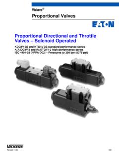
2 The Proportional spool valves of this pamphlet are designed as manifold mounting valves. They may be also combined as valve banks via the sub-plates available from consist of three functional groups. Basic dataDesign Prop. directional spool valve according to the Load-Sensing principleVersions Individual valves and valve banks (manifold mounting)Operating pressure pmax 420 bar Flow Qmax 80 (120) lpm (size 3) Qmax 160 (240) lpm (size 5)Further technical information:Size Design Pamphlet 2 Manifold mounting design D 7700-2 2 valve bank design (CAN onboard) D 7700 CAN 3 valve bank design D 7700-3 5 valve bank design D 7700-5 7 Manifold mounting design D 7700-7 FMounting; Inlet section(control section)< Size 5 ( valve bank design)= End plate > Sub-plates1.
3 General information .. 12. Type coding, overview .. 23. Available version, main data .. Connection blocks and end plates .. Add-on spool valves .. 94. Characteristic data .. General and hydraulic .. Curves .. Actuations .. Functional cut-off, prop. pressure limitation .. Other solenoid valves .. 245. Unit dimensions .. Size 3 .. 25 Size 5 .. 39 6. Appendix .. Notes for selection and lay-out .. Circuit examples .. Notes regarding assembly, installation and conversion .. 59 Table of contents<; =>D 7700-F page 22. Type coding, overviewValve section (for individual orders, without sub-plate)Inlet section (for individual order, without sub-plate)SLF 3 - A2 J 25/16 C300 / EA - G 24 PSLF A H1 F80 / 400 - 3 - G 24 Order examples: valve bankPSLF A H1 F80 / 400 /4 - 3 - A2 J 25/16 C300 /EA /3 AN320 BN320 - A2 O 80/63 F1 /EA /3 - E4 - G 24 ; Basic type coding for the valve bank or inlet section (see table 1 and 4 in sect.)
4 And ) as well as valve sections (see sect. ) PSLF A Supply with pressurized oil by means of fixed pump (open center) PSVF A Supply with pressurized oil by means of variable displacement pump (closed center) with a delivery flow controller, or as a second, separate unit if both valve banks are connected to a constant pressure system SLF Individual valve section, without sub-plate< Additional elements (acc. to table 2 and 5 in sect. ) (no coding) Basic version S, W Additional damping device in gallery LS (only with PSVF, standard with PSLF) B, B 4 .. B 7 Orifice in gallery LS (PSVF only) G Restrictor check valve (type PSLF) H Raised circulation pressure of the 3-way flow controller (approx.
5 14 bar with type PSLF)= Control oil supply (acc. to table 7, sect. ) (no coding) Without pressure reducing valve in case of an external control oil supply (min. 20 bar up to max. 40 bar) 1 With integrated pressure reducing valve for the internal supply of control oil (control pressure approx. 20 bar) 2 With integrated pressure reducing valve for the internal supply of control oil (control pressure approx. 40 bar)> Optional 2/2-way solenoid valve for arbitrary idle pump circulation (acc. to table 8, sect. ) (no coding) Without directional valve , but prepared for retrofitting F, Z, ZM = idle pump circulation when valve is de-energized D, V = idle pump circulation when valve is energized or When a pressure is specified, with pressure limiting valve which can be activated as a second pressure stage ( F 50) PA, PB, PD Prop.
6 Pressure limiting valve , with various pressure ranges? Pressure limiting valve (main pressure limitation) in the inlet section (acc. to table 9, sect. ) (no coding) Without pressure limiting valve (type PSVF only) / .. Pressure limiting valve factory set to .. bar@ Sub-plate for the inlet section (acc. to table 3, sect. ) /4, /UNF 4 Size 3, standard (tapped ports for P and R G 3/4 ISO 228/1 (BSPP) or 1 1/16-12 UN-2B SAE J 514) /6 Size 5, standard (tapped ports for P and R G 1 1/4 ISO 228/1 (BSPP)) /UNF 6 Size 5, standard (ports P and R 1 5/8-12 UN-2B SAE J 514) /7 SAE Size 5 (flange SAE 1 1/2 6000 psi)A Size (acc.)
7 To table 1 and 5, sect. ) 3 or 5 Various connection hole pattern (adapter plates enabling direct mounting between size 5 and 3 with type ZPL 53 acc. to table 10, sect. )B valve section - Basic function (acc. to table 13, section ) A 2 (standard) spool valve with inflow controller for each consumer A 1 spool valve without inflow controller, suitable for consumers, which are actuated individu-ally and successively but not simultaneously (no additional functions possible) A 5, A 7, AA 9 Inflow controller with enforced spring for higher flow A 8 4/3-way directional spool valve (pre-selector valve ) AR 2, AR 5, like A 2, A 5, A 7 but with check valve function AR 7 AX Blanking plateC Coding for the flow-pattern (acc.
8 To table 14, sect. and 6 c) L, M, F, H, J, B, R, O, P, A, Q, K, T, I, Y, Z, V, G, W, XD Flow coding for port A and B (acc. to table 15, sect. ) ../.. Coding for port A or B (independently selectable) 3, 6, 10, 16, 25, 40, 63, 80 (size 3) 16, 25, 40, 63, 80, 120, 160 (size 5) E LS-pressure limitation (deviating from the main pressure setting, lower pressure for the connected consumer) no shock valves (acc. to table 16 and 18, section ) (doesn t apply to spool valve types without inflow controller, coding A 1 B or table 12) (no coding) No secondary pressure limitation , Only for consumer port or B For consumer ports A and B Joint for consumer port A and B (not in conjunction with coding or S.
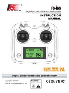
9 F )De-energized closedDe-energized openJGFEDCBA?>=;JA; <+JIHGFEDCBA@?>=<;D 7700-F page 3F Functional cut-off (acc. to table 17 and 18, sect. ) (doesn t apply to spool valve types without inflow controller, coding A1 B or table 13) (no coding) No functional cut-off F 1 Electrical cut-off, consumer port A F 2 Electrical cut-off, consumer port B F 3 Electrical cut-off, consumer port A and B FP 1(2, 3) Like F 1(2,3), however with electro-proportio-nal pressure limitation FPH 1(2, 3) Like FP 1(2,3), however with additional push-button for manual emergency actuation S, S 1 External hydraulic load signal pick-up from the control signal port U (consumer port A) and W (consumer port B) G Types of actuation (acc.
10 To table 19 and 20, sect. ) /A Manual actuation /E Electro-hydraulic actuation /EI Like /E however without stroke limita-tion /EA Electro-hydraulic and manual actuation /E0A Like /EA, however without actuation solenoid (prepared for retrofitting) /H, /F Hydraulic actuation /H UNF, /F UNF Like /H, /F however with port thread 7/16-20 UNF-2B SAE-4 (conf. SAE J 514) /HA, /FA Hydraulic, (solenoid) and manual actuation /HA UNF, /FA UNF Like /HA, /FA however with port thread 7/16-20 UNF-2B SAE-4 (conf. SAE J 514) /HEA, /FEA Hydraulic and electric actuation /HEA UNF, /FEA UNF Like /HEA, /FEA however with port thread 7/16-20 UNF-2B SAE-4 (conf.