Transcription of Proportional directional valves - Atos
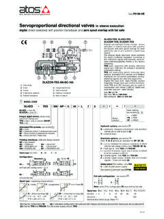
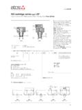
1 directional valves digital , direct operated, open loop, with positive spool overlapTable FS160-1/EDKZOR-AES-BC-171 Series numberDHZODHZO = size 06 DKZOR = size 10A = open loopValve size- ISO 4401: 0 = 061 = 10 Nominal flow (l/min) at Dp 10bar P-T-//---1 MODEL CODE for STANDARD SPOOLSAB USB connectorFieldbus connectorMain connector Spool type- regulating characteristics:Seals material, see , 6:-=NBRPE= FKM BT = HNBR Hydraulic options - see :B = solenoid and integral electronics at side of port A (3)Y = external drainHand lever options, only forA - see sect. :MO = horizontal hand leverMV = vertical hand leverBMO = horizontal hand lever installed at side of port ABMV = vertical hand lever installed at side of port AElectronic options, only for AEB, AES - see sect.:C = current feedback 4 20 mA for remote transducer,only in combination with option WI = current reference input 4 20 mA(omit for standard voltage reference input 10 V)Q = enable signalZ = double power supply, enable, fault and monitorsignals - 12 pin connector W = Power limitation function - 12 pin connector1110 Configuration (2):71 =73 =53 =51 =Option/BStandardAESBP071L5**FS160L = linearS= progressiveD = differential-progressive P-A = Q, B-T = Q/2P-B = Q/2, A-T = Q(1)Omit for A execution;AEBavailable only in version NP;AESavailable only in version BC, BP, EH(2)Hydraulic symbols are rapresented with integral digital driver(3)In standard configuration the solenoid (config.)
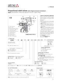
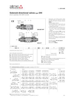
2 51 and 53) and integral electronics (AEB, AES) are at side of port BSpecial DHZO execution with max pressure 420 baravailable on requestValve bodySpoolProportional solenoidIntegral electronicsyxcv-= omit for execution with separateddriver see section 2EB = basic integral driverES = full integral driverFieldbus interfaces- USB port always present (1):NP = Not present BC = CANopenBP = PROFIBUS DP EH= EtherCATDHZO-A, DHZO-AEB, DHZO-AES DKZOR-A, DKZOR-AEB, DKZOR-AES Direct operated digital Proportional valveswithout position transducer and with posi-tive spool overlap, for open loop directio-nal controls and not compensated : Awithout integral driver, to be coupledwith separated drivers, see section 2. AEBwith basic integral digital electro-nic driver, analog reference signals andUSB port for software functional para-meters setting. AESwith full integral digital electronicdriver and fieldbus interface for functio-nal parameters setting, referencesignals and real-time integral digital electronic driverperforms the valve s hydraulic regulationaccording to the reference signal andassures valve-to-valve interchangeabilitythanks to the factory presettingSize: 06 and10 Max flow: up to 70and 160 l/minMax pressure: 350 bar (DHZO)315 bar (DKZOR)Coil voltage only for A- see sect.
3 :-= standard coil for 24 VDCAtos drivers6 = optional coil for 12 VDCAtos drivers18 = optional coil for low current drivers10*/ 14 (L)1-Spool size: DHZO =DKZOR =1 (L)4,5-2 (S)8-3 (L,S,D)18455 (L,S,D)2860 Communication interfaceUSB Atos ASCII codingCANopenEN50325-4 + DS408 PROFIBUS DPEN50170-2/IEC61158 EtherCATIEC 61158 Communication physical layernot insulatedUSB + USB OTGoptical insulatedCAN ISO11898optical insulatedRS485 Fast Ethernet, insulated100 Base TX Max. power A= 30W AEB, AES= 50W A= 35 WAEB, AES= 50W Insulation class H (180 ) Due to the occuring surface temperatures of the solenoid coils, the European standards ISO 13732-1 and EN982 must be taken into account Protection degree to DIN EN60529 IP66/67 with mating connectors Tropicalization Tropical coating on electronics PCB Duty factor Continuous rating (ED=100%) EMC, climate and mechanical load See technical table G004 DHZO-A* and DKZOR-A* Proportional valves are CE marked according to the applicable Directives ( Immunity/Emission EMC Directive andLow Voltage Directive).
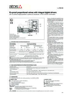
4 Installation, wirings and start-up procedures must be performed according to the general prescriptions shown in tableF003 and in the installation notes supplied with relevant NOTES ports P, A, B= 350; T= 210 (250 with external drain /Y); Y= 10ports P, A, B= 315; T= 210 (250 with external drain /Y); Y= 10 5 [% of max regulation] 1 [% of max regulation]30 Notes: above performance data refer to valves coupled with Atos electronic drivers, see section 2 (1)for different Dp, the max flow is in accordance to the diagrams in section (2)see detailed diagrams in section (3)see detailed diagrams in section CHARACTERISTICS - based on mineral oil ISO VG 46 at 50 C40<30 (at p = 100 bar); <135 (at p = 350 bar)<80 (at p = 100 bar); <600 (at p = 315 bar)Hysteresis RepeatabilityResponse time [ms](0-100% step signal)Leakage [cm3/min]Pressure limits[bar]Spool typeValve modelDHZODKZORN ominal flow[l/min]Dp= 10 barDp= 30 barDp= 70 bar(1)(3)(2)4 FIELDBUS - only for AESF ieldbus allows the direct communication of the Proportional valve with machine control unit for digital reference signal, diagnostics andsettings of functional parameters.
5 Analog reference signal remain available on the main connector for quick commissioning and detailed information about fieldbus features and specification see tech table GS510. max permissible flow Dp P-T60105160160L5,S5,D54580120120L3,S3,D3 28507070L5,S5,D518304550L3,S3,D38142130S 24,581218L111,72,64L14 Coil code DHZO DKZOR Coil resistance R at 20 C 3 3,3 W 2 2,2 W 13 13,4 W 3,8 4,1W 2,2 2,4 W 12 12,5 W Max. solenoid current 2,2 A 2,75 A 1 A 2,6 A 3,25 A 1,2 A standardoption /6option /18standardoption /6option /18 Assembly position Any position Subplate surface finishing Roughness index, Ra 0,4 flatness ratio 0,01/100 (ISO 1101) MTTFd valves according to EN ISO 13849 150 years, see technical table P007 Ambient temperature range A: standard= -20 C +70 C, /BToption = -40 C +60 C AEB, AES: standard= -20 C +60 C, /BToption = -40 C +60 C Storage temperature range A: standard= -20 C +80 C, /BToption = -40 C +70 C AEB, AES.
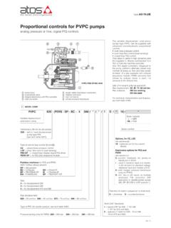
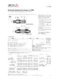
6 Standard= -20 C +70 C, /BToption = -40 C +70 C2 ELECTRONIC DRIVERSNote: For main and communication connector see sections,1314 Valve modelAAEBAESD rivers modelE-MI-AC-01FE-BM-AC-01FE-ME-AC-01FE- MI-AS-IRE-BM-AS-PSE-BM-AESE-RI-AEBE-RI-A ESTypeAnalogDigitalVoltage supply (VDC)1224122424122412242424 Valve coil option/6std/6stdstd/6std/6stdstdstdForma tplug-into solenoidDIN 43700 UNDECALEUROCARD plug-into solenoidDIN-rail panelIntegral to valveData sheetG010G025G035G020G030GS050GS1156 SEALS AND HYDRAULIC FLUID - for other fluids not included in below table, consult our technical office7 DIAGRAMS - based on mineral oil ISO VG 46 at 50 CDHZO1 = L142 = L14466 Regulated flow [l/min]Stroke [% of max]21 Hydraulic configuration vs. reference signal for configurations 71 and 73 (standard and option /B)Reference signal0 +10 VP nA / B nT 12 20 mAReference signal0 -10 V P nB / A nT 12 4 mA}}557789 DHZO7 = L58 = S59 = D5 DKZOR13 = L514 = S515 = D5 DHZO3 = S2 DKZOR10 = L311 = S312 = D3 DHZO4 = L35 = S36 = D3 Regulated flow [l/min]Regulated flow [l/min]Regulated flow [l/min]Regulated flow [l/min]Regulated flow [l/min] Regulation diagrams - values measure at Dp30 bar P-TStroke [% of max]Stroke [% of max]Stroke [% of max]Stroke [% of max]Stroke [% of max]213312111011121015141315141398FS160 Note.
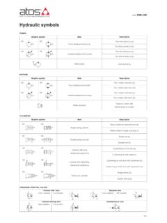
7 Seals, recommended fluid temperature NBR seals (standard) = -20 C +60 C, with HFC hydraulic fluids = -20 C +50 C FKM seals (/PE option) = -20 C +80 C HNBR seals (/BT option) = -40 C +60 C, with HFC hydraulic fluids = -40 C +50 C Recommended viscosity20 100 mm2/s - max allowed range 15 380 mm2/sFluid contamination classISO 4406 class 20/18/15 NAS 1638 class 9, in line filters of 10 mm (b10 _>75 recommended)Hydraulic fluidSuitable seals typeClassificationRef. StandardMineral oilsNBR, FKM, HNBRHL, HLP, HLPD, HVLP, HVLPDDIN 51524 Flame resistant without waterFKMHFDU, HFDRISO 12922 Flame resistant with waterNBR, Flow /Dp diagrams stated at 100% of valve strokeFlow rate [l/min]Valve pressure drop Dp [bar]Flow rate [l/min] Operating limitsFlow rate [l/min]Valve pressure drop Dp [bar]Valve pressure drop DP [bar]Flow rate [l/min]76 DKZORDHZODKZORDHZO6 = spool S3, L3, D37 = spool S5, L5, D51= spool L142= spool L13= spool S24 = spool L3, S3, D35= spool L5, S5, D56 = spool S3, L3, D37 = spool S5, L5, D51= spool L142= spool L13= spool S24 = spool L3, S3, D35= spool L5, S5, D5 Valve pressure drop Dp [bar] Response timeThe response times in below diagrams are measured at different steps of the reference input signal.
8 They have to be considered as average the valves with digital electronics the dynamics performances can be optimized by setting the internal software [ms]Time [ms]Spool stroke [%]Spool stroke [%]Step signal [%]Step signal [%]DHZODKZOR0 -1000 -750 -500 -250 -1000 -750 -500 Operation as throttle valve Single solenoid valves configuration51 and 53 can be used as simplethrottle valves :Pmax = 250 bar (option /Y advisable)214356710203040500102030405001 0203040500102030405008 PROGRAMMING TOOLS- see tech table GS500 Valve's functional parameters and configurations, can be easily set and optimized usingAtos E-SW programming software connected via USB port to the digital driver. Forfieldbus versions, the software permits valve's parameterization through USB port also ifthe driver is connected to the central machine unit via software is available in different versions according to the driver s options:E-SW-BASIC support: NP (USB) PS (Serial) IR (Infrared)E-SW-FIELDBUS support: BC (CANopen) BP (PROFIBUS DP) EH (EtherCAT) EW (POWERLINK) EI (EtherNet/IP)E-SW-*/PQ support: valves with SP, SF, SL alternated control ( E-SW-BASIC/PQ)WARNING: drivers USB port is not isolated!
9 The use of isolator adapter is highly recommended for PC protection (see table GS500)USB connectionE-C-SB-USB/M12 cableE-A-SB-USB/OPT isolatorMax flow Dp= 30bar [l/min]SPOOL TYPEDHZODKZOR1660100L1L3S3L5S528S24L1413 0170FS16011 ELECTRONIC OPTIONS forAEB andAESS tandard driver execution provides on the 7 pin main connector:Power supply - 24 VDCmust be appropriately stabilized or rectified and filtered; 2,5 Afuse time lag is required in series to each driverpower supply Apply at least a 10000 mF/40 V capacitance to single phase rectifiers or a 4700 mF/40 V capacitance tothree phase rectifiersReference input signal- analog differential input with 10 VDCnominal range (pin D, E), Proportional to desired coil currentMonitor output signal - analog output signal Proportional to the actual valve s coil current (1V monitor = 1A coil current)Note: a minimum booting time of 500 ms has be considered from the driver energizing with the 24 VDCpower supply before the valve hasbeen ready to operate.
10 During this time the current to the valve coils is switched to Option /IIt provides 4 20 mA current reference signal, instead of the standard 10 signal can be reconfigured via software selecting between voltage and current, within a maximum range of 10 V or 20 is normally used in case of long distance between the machine control unit and the valve or where the reference signal can be affected byelectrical noise; the valve functioning is disabled in case of reference signal cable Option /QTo enable the driver, supply 24 VDCon pin C referred to pin B: Enable input signal allows to enable/disable the current supply to the solenoid,without removing the electrical power supply to the driver; it is used to maintain active the communication and the other driver functions whenthe valve has to be disabled. This condition does not comply with European Norms EN13849-1 (ex EN954-1). Option /ZIt provides, on the 12 pin main connector, the following additional features: Enable Input Signal To enable the driver, supply 24 VDCon pin 3 referred to pin 2: Enable input signal allows to enable/disable the current supply to the solenoid,without removing the electrical power supply to the driver; it is used to maintain active the communication and the other driver functions whenthe valve has to be disabled.