Transcription of Proportional Pressure Relief Valves - Eaton
1 Proportional Pressure Relief Valves Technical Catalog KBCG-6-1*. KBCG-8-1*. Contents General Description Page 3. Typical Section Page 3. Functional Symbol Page 4. Model Codes Page 5. Operating Data Page 6. Performance Data Pressure Override, Off-Load Page 8. Pressure Override when Relieving Page 9. Pressure Gain Page 9. Step Response Page 9. Installation Dimensions KBCG-6/8 Models Page 10. Mounting Surfaces Page 11. CGVM-6-10-R Subplate Page 11. Electrical Information Block Diagram Page 12. Typical Connection Arrangements Page 13. Further Information Page 14.
2 This product has been designed and tested to meet specific standards outlined in the European Electromagnetic Compatibility Directive (EMC) 89/336/EEC, amended by 91/263/EEC, 92/31/EEC and 93/68/EEC, article 5. For instructions on installation requirements to achieve effective protection levels, see this leaflet and the Installation Wiring Practices for Vickers Electronic Products leaflet 2468. Wiring practices relevant to this Directive are indicated by Electromagnetic Compatibility (EMC). 2 Eaton Vickers Proportional Pressure Relief Valves V-VLPO-MC003-E May 2003.
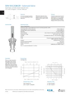
3 General Description These two-stage Pressure Relief command. The amplifier is Mounting face to ISO 6264: Low installed cost and space Valves offer extensive mounted in a robust metal For AR-06-2-A requirement from high application possibilities through housing and electrical For AS-08-2-A power/size ratios (more than their ability to control the connections are via an industry double that of many Pressure setting in proportion standard 7-pin plug. Factory-set conventional designs). to an applied electrical input (up adjustments ensure high Features and Benefits On-board ramp adjustment.)
4 To a Pressure limit which is reproducibility valve-to-valve. Remote electrical Proportional manually adjustable and control of Pressure from a lockable). Basic Characteristics choice of five Pressure ranges The integral amplifier allows the per valve size. Max. bar Pressure to be controlled from (5000 psi) Excellent repeatability and a low power command signal: stable performance results either a voltage or current Max. flow L/min from cartridge design of (106 USgpm) mainstage elements. Typical Section Eaton Vickers Proportional Pressure Relief Valves V-VLPO-MC003-E May 2003 3.
5 Functional Symbols Manual and electrical Manual and electrical pilots internally pilots drained to side drained to port T. drain port . Model code 7 = Blank Model code 7 =1. 7-pin plug 7-pin plug P T P T. Side drain port . X P T X P T. Tapped port on side of pilot head. Manual pilot internally drained to port T;. electrical pilot drained to side drain port . Model code 7 =3. 7-pin plug P T. Side drain port . X P T. Tapped port on side of pilot head. 4 Eaton Vickers Proportional Pressure Relief Valves V-VLPO-MC003-E May 2003. Model Codes 1 Valve Type 6 Controlled Pressure 9 Electrical Command 14 Design Number, 1* Series Range Options KB - Proportional valve Subject to change.
6 Installation with integral amplifier, Based on inlet Pressure of 350 bar 1 - +/- 10 volts control signal dimensions unaltered for design B series (5000 psi). numbers 10 to 19 inclusive. 2 - 4-20 mA control signal Note, with 100 bar (1450 psi) inlet the lower limits will be 2-3 bar 2 Type (30-43 psi) lower Warning 40 - 6-40 bar (87-580 psi) 10 Ramps C - Pressure Relief To conform to the EC. 100 - 7,75-100 bar (112-1450 psi) 3 - Standard ramp for KBCG- Electromagnetic 6/8 valve types 160 - 8,5-160 bar (125-2300 psi) Compatibility directive (EMC) this KBCG valve must be fitted with a 3 Mounting 250 - 8,5-250 bar (125-3625 psi) metal 7-pin plug.
7 The screen of the G - Subplate mounted 350 - 9-350 bar (139-5000 psi) 11 Command/ Pressure cable must be securely connected Characteristic to the shell of the metal connector. A suitable IP67 rated connector is A - Standard available from Eaton , part no. 4 Interface - ISO 6264 7 Drain 934939. Alternatively a non IP67. Blank - Manual and electrical rated connector is available from With B port high Pressure inlet, pilots drain internally ITT-Cannon, part no. CA 02 COM-E. A port reduced Pressure outlet 12 Electrical Connection to T port 14S A7 P.
8 6 - AR-06-2-A PC7 - 7 pin connector, without 1 - Manual and electrical plug supplied 8 - AS-08-2-A pilots drained to side port drain PE7 - 7 pin connector, with 3 - Manual pilot internally plug supplied 5 Manual Adjustment drained to T port, PH7 - As PE7 but with pin C'. electrical pilot drained to used for enable signal K - Micrometer with keylock side port drain M - Micrometer without PR7 - as PC7 but with pin C'. keylock used for enable signal W - Screw/locknut 8 Standard Features ZM - for KBC 13 Coil Rating H1 - 24V DC amplifier supply Eaton Vickers Proportional Pressure Relief Valves V-VLPO-MC003-E May 2003 5.
9 Operating Data Standard test conditions are with antiwear hydraulic oil at 36 cSt (168 SUS) and 50 C (122 F). Maximum pressures: Ports P and X 350 bar (5000 psi). Port T in KBCG-*-**-Z Valves 2 bar (30 psi). Port T in KBCG-*-**-1/3-Z Valves 350 bar (5000 psi). Side drain port 2 bar (30 psi). Back Pressure at these ports additive to the Pressure setting of the valve. Rated flow at p = 6 bar (87 psi): KBCG-6 200 L/min ( USgpm). KBCG-8 400 L/min ( USgpm). Vent flow with valve at rated flow 1 L/min ( USgpm). See Venting , page 8. Pilot control drain flow, when valve is limiting system Pressure , flow P to T occurring: KBCG-6 1,3 L/min ( USgpm).
10 KBCG-8 2,0 L/min ( USgpm). Coil or amplifier rating 24V x 40W max. (22 to 36V including 10% max. ripple). Command signal: Volts (see model code 9 - 1) 0 to +10V or 0 to -10V. Input impedance 47 k . Common mode voltage to pin B 4V. Current (see model code 9 - 2) 4 to 20 mA. Input impedance 100 . Valve enable signal: Enable > (36V max). Disable < Input impedance 36 k . 7-pin plug connector Pin Description A G. A Power supply positive (+). F B B Power supply 0V and current command return C Valve enable (PH7 & PR7). E C D Command signal (+V or current in).