Transcription of Proportional relief valves - Atos
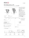
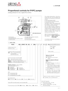
1 relief valves with integral pressure transducerdigital, pilot operated, closed loop high performances, rugged designTable FS040-2/EProportional pressurerelief valve, two stageR = closed loop pressure control-= omit for execution with separated driversee section EB= basic integral driverES= full integral driverValve size ISO 626410, 20, 32 Hydraulic options, see section :E = external pilotY= external drain (only pipe connection G1/4 ) Electronics options only forREBandRES- see section :I= current reference input and monitor 4 20 mA (omit for standard voltage reference input 0 10 V)Q = enable signalZ= double power supply, enable, fault and monitorsignals - 12 pin connector141 MODEL CODEFS040 Max regulated pressure:100 = 100 bar210= 210 bar315= 315 bar350= 350 barAGMZO-RES-P-BC-20 Valve main bodyMain poppetMechanical pressure limiterDrain port G 1/4 (option /Y) Proportional solenoid Integral pressure transducerIntegral electronicsUSB connectorFieldbus connectorMain connectorScrew for air bleeding AGMZO/ // /----RPNPEB10315**Seals material, see sect.
2 , :-=NBR PE= FKMBT = HNBRF ieldbus interfaces- USB port always present (1):NP = Not present BP = PROFIBUS DPBC = CANopen EH= EtherCATP = with integral pressure transducerSeries number 2 ELECTRONIC DRIVERSV alve modelData sheetDrivers modelE-RI-REBREBNote: for main and communication connectors see sections ,1617E-BM-RESGS203 RTypeFormatIntegral to valveDIN rail panel formatDigitalE-RI-RESGS205 RESH ydraulic symbolAGMZO-REBAGMZO-RESAGMZO-RAGMZO-R, AGMZO-REB, AGMZO-RESP oppet type pilot operated digital Proportional relief valves with integralpressure transducer for pressure closedloop controls. Executions: Rwithout integral driver, to be coupledwith separated driver type E-BM-RES,see table GS203 REBwith basic integral digital electro-nic driver, analog reference signals andUSB port for software functional para-meters setting RESwith full integral digital electronicdriver and fieldbus interface for functio-nal parameters setting, referencesignals and real-time diagnosticsThe integral digital electronic driverperforms the valve s hydraulic regulationaccording to the reference signal andassures valve-to-valve interchangeabilitythanks to the factory presettingSize: 10, 20, 32 Max flow.
3 200, 400, 600 l/minMax pressure: 350 barPT XXY(1)Omit for R execution;REBavailable only in version NP;RESavailable only in version BC, BP, EHDynamic response presetsee section :-= omit for PID 1 fast (default)2= PID 2 standard3= PID 3 smooth125 MAIN CHARACTERISTICS - based on mineral oil ISO VG 46 at 50 C20040060080100115 0,5 1,0 0,2zero point displacement < 1% at DT = 40 CValve sizeMax regulated pressure [bar]Min. regulated pressure [bar]Max. pressure at port P [bar]Max. pressure at port T [bar]Max. flow [l/min]Response time 0-100% step signal (1) [ms](depending on installation) Hysteresis [% of the max pressure]Linearity [% of the max pressure]Repeatability [% of the max pressure]Thermal drift 10100; 210; 315; 3502032see min.
4 Pressure/flow diagrams at section 350210 Mineral oilsHydraulic fluidNBR, FKM, HNBRFKMNBR, HNBRDIN 51524 ISO 12922HL, HLP, HLPD, HVLP, HVLPDHFDU, HFDRHFCS uitable seals typeClassificationRef. StandardFlame resistant without waterFlame resistant with water6 SEALS AND HYDRAULIC FLUID - for other fluids not included in below table, consult our technical office NBR seals (standard) = -20 C +60 C, with HFC hydraulic fluids = -20 C +50 C Seals, recommended fluid temperature FKM seals (/PE option) = -20 C +80 C HNBR seals (/BT option)
5 = -40 C +60 C, with HFC hydraulic fluids = -40 C +50 C Recommended viscosity 20 100 mm2/s - max allowed range 15 380 mm2/s Fluid contamination class ISO 4406 class 20/18/15 NAS 1638 class 9, achievable with in line filter - 10 mm (b10 _>75 recommended)AGMZO-R* Proportional valves are CE marked according to the applicable Directives ( Immunity/Emission EMC Directive and Low VoltageDirective). Installation, wirings and start-up procedures must be performed according to the general prescriptions shown in table F003 and inthe installation notes supplied with relevant electrical signals of the valve ( monitor signals) must not be directly used to activate safety functions or components, as prescribed bythe European standards (Safety requirements of fluid technology systems and components-hydraulics, EN-982).
6 3 GENERAL NOTES(1) Average response time value; the pressure variation in consequence of a modification of the reference input signal to the valve is affectedby the stiffness of the hydraulic circuit: greater is the stiffness of the circuit, faster is the dynamic response, see section 12 Notes: above performance data refer to valves coupled with atos electronic drivers, see section . Assembly position Any position Subplate surface finishing Roughness index, Ra 0,4 flatness ratio 0,01/100 (ISO 1101) MTTFd valves according to EN ISO 13849 75 years, see technical table P007 Ambient temperature range R: standard= -20 C +70 C, /BToption = -40 C +60 C REB, RES: standard= -20 C +60 C, /BToption = -40 C +60 C Storage temperature range R.
7 Standard= -20 C +80 C, /BToption = -40 C +70 C REB, RES: standard= -20 C +70 C, /BToption = -40 C +70 C Coil resistance R at 20 C 3 3,3W Max. solenoid current 2,6 A Max. power R= 30 WattREB, RES= 50 Watt Pressure transducer E-ATR-8/*/I output signal = 4 20 mA - see tech. table GS465 Insulation class H (180 ) Due to the occuring surface temperatures of the solenoid coils, the European standards ISO 13732-1 and EN982 must be taken into account Protection degree to DIN EN60529 IP66/67 with mating connectors Tropicalization (only REB, RES) Tropical coating on electronics PCB Duty factor Continuous rating (ED=100%)
8 EMC, climate and mechanical load See technical table G004 Communication interface (only REB, RES)USB atos ASCII codingCANopenEN50325-4 + DS408 PROFIBUS DPEN50170-2/IEC61158 EtherCATIEC 61158 Communication physical layer (only REB, RES) not insulatedUSB + USB OTGoptical insulatedCAN ISO11898optical insulatedRS485 Fast Ethernet, insulated100 Base TX4 FIELDBUS - only for RESF ieldbus allows the direct communication of the Proportional valve with machine control unit for digital reference signal, diagnostics andsettings of functional parameters. Analog reference signal remain available on the main connector for quick commissioning and detailed information about fieldbus features and specification see tech table GS510.
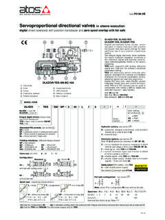
9 7 DIAGRAMS (based on mineral oil ISO VG 46 at 50 C)3-8 = Min. pressure/flow diagrams with zero reference signal 3 = AGMZO-*-10/100, 210, 315 4 = AGMZO-*-10/350 5 = AGMZO-*-20/100, 210, 315 6 = AGMZO-*-20/350 7 = AGMZO-*-32/100, 210, 315 8 = AGMZO-*-32/3501 = Regulation diagrams with flow rate Q = 50 l/min2 = Pressure/flow diagrams with reference signal set at Q = 50 l/minPressure at port P [bar]Flow [%]21 Pressure at port P [% of the max]Reference signal [% of the max]Min. regulated pressure [bar]Flow [l/min]Min. regulated pressure [bar]Flow [l/min]357468FS0408 HYDRAULIC Option EExternal pilot option to be selected when the pilot pressure is supplied from a differentline respect to the P main option E the internal connection between port P and X of the valve is pilot pressure must be connected to the X port available on the valve s moun-ting surface or on main body (threaded pipe connection G ).
10 Option YThe external drain is mandatory in case the main line T is subjected to pressure peaksor it is Y drain port has a threaded connection G available on the pilot stage plug SP-X100A9 MECHANICAL PRESSURE LIMITERThe AGMZO are provided with mechanical pressure limiter acting as protectionagainst overpressure. For safety reasons the factory setting of the mechanical pres-sure limiter is fully unloaded (min pressure).At the first commissioning it must be set at a value lightly higher than the max pres-sure regulated with the Proportional the pressure setting of the mechanical pressure limiter, proceed according tofollowing steps: apply the max reference i