Transcription of Propulsion (1): Jet Engine Basics - SmartCockpit
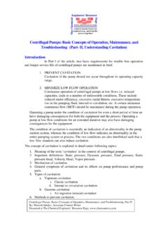
1 P1, Page 1 FLIGHTOPERATIONSENGINEERINGP ropulsion (1): Jet Engine BasicsP1, Page 2 Jet Engine Fundamentals (Videos) Types of Jet Engines Propulsive Efficiency and the Thrust Equation More Engine TerminologyPropulsion (1): Jet Engine BasicsP1, Page 3 Pratt & Whitney Videos on Jet Engine Fundamentals1 - The concepts of thrust 2 - Typical Turbo Jet Engines 3 - Variations in Jet Engine Design 4 - Types of Gas Turbine Engines P1, Page 4 What is a Jet Engine ? A jet Engine is a machine designed for the purpose of creating large volumes of high-velocity exhaust gasses. (This sounds simplistic, but it is essentially correct.) This is done in order to produce the thrust needed to overcome the aerodynamic drag of an airplane. In the process of producing high-velocity exhaust, the jet Engine also produces: Electrical power Hydraulic power Pneumatic power for A/C and pressurization Hot air for anti-icing protectionP1, Page 5 basic operation of a Jet Engine The basic operation of a jet Engine is: Air enters and is compressed in a compressor.
2 Fuel is then added and ignited. The resulting gas spins a turbine, The turbine powers the compressor. The gas then exits the Engine at the tailpipe. The way a jet Engine operates is similar to the way an automobile Engine operates: Intake, compression, ignition, , Page 6 The Engine shown here is known as a Whittle type Engine , since it follows the original design features developed by Sir Frank Whittle in the 1930 s. The first flight of a jet Engine of his design was in 1941. All engines in use on today s commercial jet airplanes have beendeveloped based on this original of the Jet EngineP1, Page 7 Types of Jet Engines The earliest commercial (paying passenger-carrying) jet airplanes used a single-spool turbojet Engine , like that shown below. The term single spool refers to the fact that there is only one shaft. This shaft connects one turbine section to one compressor , Page 8 Types of Jet Engines All jet engines in current use are axial flowengines, meaning that the compression phase is done axially (parallel to the axis of the Engine ) as the air flows through the compressor.
3 Axial flow engines are different from early jet engines which compressed air in a centrifugal , Page 9(suck)(squeeze)(bang)(whoosh!)Thermodyn amic Cycles Through a Jet Engine Similar to a Four-Stroke EngineP1, Page 10 Twin-Spool Turbojet Engine The first significant development after the introduction of the early axial-flow, single-spool turbojets was the introduction of a second shaft. This second shaft allowed the Engine to have two independent stages of compression powered by two independent turbines. The compressors and turbines could now be more accurately matched to the characteristics of the airflow through the Engine , creating an improvement in , Page 11 Twin-Spool Turbojet Engine The first stage of compression is the low-speed rotor, and the second stage is the high-speed rotor. These terms refer to the fact that the first stage of the turbine, which rotates the second stage compressor, turns at a faster rate than the second stage turbine/first stage compressor.
4 These are often referred to as the N1 rotor (low-speed) and the N2 rotor (high-speed).P1, Page 12 Turbofan Engine The next significant development was the introduction of the turbofan Engine . In a turbofan Engine , a portion of the thrust is developed by the fan which is, in effect, a multi-bladed propeller, rotated by the N1 turbine. A large portion of the air which is accelerated by the fan stage does not progress through the rest of the Engine . The fan accelerates a large amount of air mass by a relatively small amount. This is more efficient then accelerating a smaller volume of air by a larger , Page 13 Turbofan Engine The bypass ratio is the ratio of the air which exits the enginewithout going through the rest of the Engine core compared to the amount of air which goes through the Engine core (the primary flow). Each of these produces thrust.
5 Turbofan engines produce lower noise levels than earlier engines, and have considerably improved fuel By-pass Turbo-jet (low by-pass ratio) P1, Page 14 High Bypass Ratio Turbo Fan Engine Early turbofan engines were low-bypass ratio engines. Approximately of the thrust was produced by the fan stage, and the other half by the primary flow. Engines currently in production for most commercial airplanes are all high-bypass ratio turbofans. The difference is that these engines have a much higher ratio of bypass (fan stage) air compared to the primary air. Current bypass ratios are around 5:1 and higher. For these engines, the fan stage provides about 75 to 80 percent of the total thrust produced by the , Page 15 High Bypass Ratio Turbofan EngineHigh Bypass Ratio Turbo Fan EngineHigh bypass ratio engines take in a large amount of air and accelerate it only a small amount (relative to low bypass ratio engines).
6 P1, Page 16PW4084 bypass ratioRR Trent 800 bypass ratioHigh Bypass RatioTurbo Fan EnginesP1, Page 17GE-90B Engine :9:1 bypass ratioHigh Bypass Ratio Turbo Fan EnginesP1, Page 18 High Bypass Ratio Turbo Fan EnginesP1, Page 19 High Bypass Ratio Turbo Fan EnginesP1, Page 20 Triple Spool Turbofan Engines RR engines now in production use a triple-spool design, incorporating three independent rotors. Designed to achieve better fuel economy due to the ability of the triple-spool design to better match the design of the compressors and turbines to the , Page 21 Propulsive EfficiencyThe propulsive efficiency of an Engine can be expressed in terms of the inlet velocity of the air and the exhaust Engine (Vinlet+ Vexit)2*Vinlet p=P1, Page 22 Propulsive Efficiency An efficiency of 100% would be attained if the exhaust velocity was equal to the inlet velocity.
7 However, for this to occur, themass flow through the Engine would need to be infinite. Infinite mass flow is obviously not achievable in the real world, but this does indicate that greater efficiency is obtained when a large mass of air is accelerated by a small amount rather than a small mass of air being accelerated by a large amount. The high-bypass ratio Engine is a way to achieve the acceleration of a large mass of air by a small amount, thus helping the Engine to achieve greater efficiency than a low-bypass ratio Engine can , Page 23 The Thrust Equation Recall from Newton's third law: For every action there is an equal and opposite reaction The jet Engine 's actionis accelerating a mass of gas and sending it out tailpipe. The equal and opposite reactionis , Page 24 The Thrust Equation Recall from Newton s second law: In jet Engine terms, we can re-write this as: Where:Fis force in poundsw is the gas flow in pounds per secondg is the gravitational constantV1is the initial velocity of the gas, in ft/secV2is the final velocity of the gas, in ft/secF =wg*(V2 V1)yyF = d(mv)/dt (= ma for a constant mass)P1, Page 25 The Thrust Equation Note that instead of using F = ma, we are re-writing the equation as force equals mass flowper unit time multiplied by velocity change.
8 This difference is subtle but essential: Acceleration is not the same as velocity change. Thus force is notequal to mass times velocity change; acceleration is velocity change per unit of time. Using F = mass flow per unit time multiplied by velocity change is dimensionally , Page 26 The Thrust EquationWe can re-write the thrust equation to make it more meaningful in the context of a jet Engine :Fnet=wair+ wfuelg*VjetexhaustyyVairplane*wairgy-thr ust ofenginevelocityof incomingmass flowincomingmass flowof airexhaustvelocitytotal massflow outtailpipeP1, Page 27 The Thrust Equation This is called the net thrust, because it accounts for the momentum of the incoming air; Gross thrust is given by the first term in the equation which is the force created at the exhaust of the Engine . To compute usable thrust, the gross thrust has to be reduced by the amount of the second term, which is the momentum already existing because of the airplane s speed.
9 From the equation, you can see that net thrust is a function of the mass flow rate of the air and fuel passing through the Engine , and of the exhaust velocity minus the incoming , Page 28 The thrust equation as written is somewhat simplified in that itignores one more possible component of thrust. That component is thrust due to internal pressure. Most of the internal pressure within the Engine is converted to velocity of the exhaust gasses, which in turn produces thrust. At the exhaust, if the total pressure of the gasses is greater than the total pressure at the intake, this surplus of pressure will produce some additional thrust. This component of thrust is small compared to the thrust due to exhaust velocity, but should not be = Aexhaust*pexhaust-pambientAdditional Thrust Due to Internal PressureP1, Page 29 Air TemperatureThrustAltitudeThrusttropopaus eFactors Affecting ThrustAir density, a function of temperature and pressure altitude, is a very significant component affecting , Page 30 Factors Affecting Thrust Velocityaffects both the momentum and the pressure of the air entering the Engine intake.
10 Increasing aircraft speed increases the momentum of the incoming air, lowering thrust, while at the same time compressing the air at the intake (ram effect) increasing thrustby increasing density. The combined effect is show Thrustwithout ramwith ram100 %0 %P1, Page 31 Other Factors Affecting Thrust Bleed air extraction affect thrust (bleeds will be discussed later) Power extraction for hydraulic pumps, electric generators, fuel pumps, etc., affects thrust. Humidity has a negligible effect on , Page 32 Installed Thrust The performance of an Engine on the manufacturer s test stand is not the same as the performance of that same Engine when installed on an airplane. The installed Engine is different in several aspects: The test stand Engine uses an ideal bell-mouth air inlet. This has different airflow characteristics from the production inlet on an installed Engine .