Transcription of Prosonic S FMU90 - Endress+Hauser
1 ProductsSolutionsServicesTI00397F/00/ InformationProsonic S FMU90 Ultrasonic measurementA universal device for level/flow measurement and pump controlTransmitter for up to 2 sensors FDU90/91/91F/92/93/95 Field of applicationLevel measurement of fluids and bulk materials with 1 or 2 sensors for measuring of up to 45 m (148 ft) and level limit detection. Pump control, rake control and as option: additional pump control function. Calculations: average , difference, sum Application flow: Flow measurement in open channels and weirs with 1 or 2 sensors Flow measurement with back water or sludge detection Up to 3 totalizers and 3 counters Counting or time pulse output for control of external units Transmitter available with field housing or top hat rail housing for control cabinet instrumentationBenefits Simple, menu-guided operation with 6-line plain text display, 15 languages selectable Envelope curves on the display for simple diagnosis Easy operation, diagnosis and measuring point documentation with the supplied "FieldCare" operating program Time-of-flight correction via integrated or external temperature sensors Linearisation (up to 32 points, freely configurable)
2 For the most common flumes and weirs pre-programmed and selectable Online calculation of the flume-/weir-flows via integrated flow curves Field housing aluminium with ATEX II 3D certificateProsonic S FMU902 Endress+HauserTable of ContentsSafety symbols ..3 Function and system design ..4 measuring principle .. 4 Blocking distance .. 4 Time-of-flight correction .. 4 Interference echo suppression .. 4 Pump control .. 4 Linearization .. 5 Special functions .. 5 Datalog functions .. 5 Application examples for level measurements .. 6 Application examples for flow measurements .. 7 System integration HART .. 8 System integration PROFIBUS DP .. 8 Input ..9 Sensor inputs .. 9 External limit switches (option) .. 9 External temperature sensor .. 9 Output .. 10 Analog outputs .. 10 Relay outputs .. 10 PROFIBUS DP interface .. 11 Power supply .. 11 Supply voltage / Power consumption / Current consumption 11 Galvanic isolation.
3 11 Fuse .. 11 Electrical connection.. 12 Terminal compartment of the field housing polycarbonate .. 12 Cable entries of the field housing polycarbonate .. 12 Terminal compartment of the field housing aluminium .. 12 Terminal compartment of the DIN-rail housing .. 13 Terminal assignment .. 15 Connection of the sensors FDU9x .. 18 Synchronization line .. 19 Connection of the separate display and operating module .. 19 Connection of external switches(for FMU90 -**B**) .. 20 Connection of a temperature sensor .. 20 Performance characteristics .. 24 Reference operating conditions .. 24 Maximum measuring error .. 24 measuring error .. 24 Measured value resolution .. 24 measuring frequency .. 24 Influence of the vapor pressure .. 24 Environment .. 24 Ambient temperature .. 24 Storage temperature .. 24 Climate class .. 24 Vibration resistance .. 24 Ingress protection.
4 25 Electromagnetic compatibility (EMC) .. 25 Mechanical construction .. 25 Housing versions .. 25 Dimensions of the field housing polycarbonate .. 25 Dimensions of the field housing aluminium .. 26 Dimensions of the DIN-rail housing .. 26 Dimensions of the separate display and operating module .. 28 Weight .. 28 Materials .. 28 Operability .. 30 Display and operating module .. 30 Operating menu .. 30 Basic setup .. 31 Locking of the instrument .. 31 Certificates and Approvals.. 32CE mark .. 32 RoHS .. 32 RCM-tick mark .. 32 EAC conformity .. 32Ex approval .. 32 External standards and guidelines .. 32 Ordering information .. 33 Scope of delivery .. 33 Accessories .. 33 Commubox FXA195 HART .. 33 Commubox FXA291 .. 33 Protection cover for the field housing polycarbonate .. 33 Mounting plate for the field housing polycarbonate .. 34 Mounting bracket .. 34 Adaption plate for remote display.
5 35 Overvoltage protection HAW562 .. 35 Temperature sensor Omnigrad S TR61 .. 38 Documentation .. 39 Technical Information .. 39 Operating instructions(for transmitter FMU90 ) .. 39 Description of Instrument Functions .. 39 Safety Instructions .. 39 Prosonic S FMU90 Endress+Hauser3 Safety symbolsSymbolMeaningA0011189-DEDANGER!Th is symbol alerts you to a dangerous situation. Failure to avoid this situation will result in serious or fatal !This symbol alerts you to a dangerous situation. Failure to avoid this situation can result in serious or fatal !This symbol alerts you to a dangerous situation. Failure to avoid this situation can result in minor or medium !This symbol contains information on procedures and other facts which do not result in personal protectionMeaning0 Device certified for use in explosion hazardous areaIf the device has this symbol embossed on its name plate it can be installed in an explosion hazardous area-Explosion hazardous areaSymbol used in drawings to indicate explosion hazardous areas.
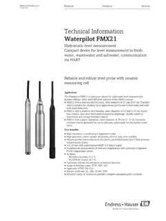
6 Devices located in and wiring entering areas with the designation explosion hazardous areas must conform with the stated type of area (non-explosion hazardous area)Symbol used in drawings to indicate, if necessary, non-explosion hazardous areas. Devices located in safe areas still require a certificate if their outputs run into explosion hazardous areasDANGERWARNINGCAUTIONNOTICEP rosonic S FMU904 Endress+HauserFunction and system designMeasuring principleL00-FMU90xxx-15-00-08-xx-9001 FDU9x2 Prosonic S FMU90BD: blocking distance, D: distance from sensor membrane to fluid surface, E: empty distance F: span (full distance),L: level, V: volume (or mass), Q: flowThe sensor transmits ultrasonic pulses in the direction of the product surface. There, they are reflected back and received by the sensor. The transmitter Prosonic S measures the time t between pulse transmission and reception. From t (and the velocity of sound c) it calculates the distance D from the sensor membrane to the product surface:D = c t/2 From D results the desired measuring value: Level L Volume V Flow Q across measuring weirs or open channelsBlocking distanceThe span F may not extend into the blocking distance BD.
7 Level echoes within the blocking distance range can not be evaluated due to the transient characteristics of the sensor. The blocking distances of the individual sensors are given in the following documents:The blocking distances of the individual sensors are given in the following documents: TI00396F for the sensors FDU90/91/91F/92/93/951)Time-of-flight correctionIn order to compensate for temperature dependent time-of-flight changes, a temperature sensor (NTC) is integrated in the ultrasonic , the Prosonic S FMU90 has an input for an external temperature sensor( FMU90 -**B**). The following sensor can be connected: Pt100 Omnigrad S TR61 from Endress+HauserThe external sensor must be used for the heated version of the ultrasonic sensors FDU90 and echo suppressionThe interference echo suppression feature of the Prosonic S ensures that interference echoes ( from edges, welded joints and installations) are not interpreted as a level controlIndividually configurable for each pump.
8 Pump switching delay, to prevent overload of the power supply system Backlash time and backlash interval, for complete draining of shafts or channels Crust reduction at pump shaft walls by fine adjustment of the switch point100%0%DLFEBDVQD12211) The sensors FDU80/80F/81/81F/82/83/84/85/86/96 are not available the serial number of your device to access the documentation for your device via S FMU90 Endress+Hauser5 LinearizationPre-programmed linearization curvesTypes of vessels Horizontal, cylindrical tank Spherical tank Tank with pyramidal bottom Tank with conical bottom Tank with flat, inclined bottomFlow curves for flumes and weirs2) Khafagi-Venturi flume ISO-Venturi flume BST3)-Venturi flume Parshall flume Palmer-Bowlus flume Rectangular weir Rectangular constricted weir NFX4) rectangular weir NFX rectangular constricted weir Trapezoidal weir V-notch weir BST V-notch weir NFX V-notch weirThe pre-programmed linearization curves are calculated formula for flow measurements Q = C (h + h )"h" is the upstream level.
9 The parameters , , and C can be freely tableconsisting of up to 32 linearization points; to be entered manually or functions limit detection rake control alternating pump control or control according to pump rate (standard) option: additional pump control functions5): Alternation accordint to runtime or starts pump feedback via the optional digital inputs; stand-by pump configurable pump function test after resting time storm function to prevent unnecessary pump running times flush control for regular pump shaft cleaning pump control according to tariff times via digital input output of operating hours alarm or pump alarm recording of pump data (operating hours, number of starts, last running time) totalising of the flow volume with (resettable) counters and (non-resettable) totalisers triggering of a sampler by time or quantity pulses low flow cut off backwater detection in flumes sludge detection in flumes trend detectionDatalog functions Peak hold indicator of the levels or flows and the temperatures at the sensors Recording of the last 10 alarms Indication of the operating status Trend indication of the outputs on the on-site display Indication of the operating hours2)
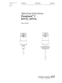
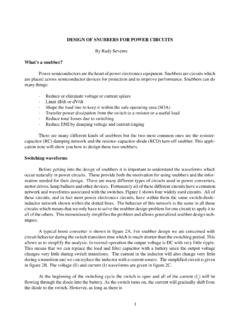
10 For instrument versions with flow software ( FMU90 - *2** or FMU90 -*4**)3) BST: British Standard4) French standard NFX 10-3115) for instruments with software for additional pump control ( FMU90 -*3** or FMU90 -*4**) Prosonic S FMU906 Endress+HauserApplication examples for level measurementsLevel measurement with limit detection and alarm outputL00-FMU90xxx-15-00-00-xx-010 Order code : FMU90 - *1**131**(1 input, 3 relays, 1 outputs) average level measurementL00-FMU90xxx-15-00-00-xx-003 Order code : FMU90 - *1**212**(2 inputs, 2 outputs)minProsonic SmaxminLFDU9xLmaxProsonic SL1 + L22L1L2 Rake control(differential measurement)L00-FMU90xxx-15-00-00-xx-004 Order code : FMU90 - *1**212**(2 inputs, 1 relay, 2 outputs)Alternating pump control(up to 6 pumps)L00-FMU90xxx-15-00-00-xx-007 Order code : FMU90 - *1**131**(1 input, 3 relays) Prosonic SD1D2 MLProsonic SConveyor beltL00-FMU90xxx-15-00-00-xx-005 Order code : FMU90 - *1**111**(1 input, 1 output)DProsonic SProsonic S FMU90 Endress+Hauser7 Application examples for flow measurementsPulses for volume counter + time pulses ( for sampler)L00-FMU90xxx-15-00-00-xx-011 Order code : FMU90 - *2**131**(1 input, 3 relays, 1 output)Flow measurement with backwater alarm or sludge detectionIf the ratio "downstream level:upstream level" rises above or falls below a critical value, an alarm will be code : FMU90 - *2**212**(2 inputs, 1 relay, 2 outputs)FDU9xDQProsonic S123m3 QProsonic SStormwater overflow bassinSimultaneous measurement of level L and flow Q with 1 code : FMU90 - *2**112**(1 input, 2 outputs)LQ(l/s)L (m)Q (l/s) Prosonic S123m3 Prosonic S FMU908 Endress+HauserSystem integration HARTO perating optionsIn the standard version a HART signal is superimposed onto the first output current.