Transcription of Protocol for Communication with Peripheral - …
1 EUROMAP 66-1 Protocol for Communication with PeripheralEquipmentGeneral DescriptionVersion , December 2002(10 pages)This recommendation was prepared by the Technical Commission of 66-1 General DescriptionVersion 66-1 Page 2 of 10 HistoryDateChangesJune 2002 Document of some typing representation of hex 2002 Power supply 24V DC for the CAN network is optional (see ); Fig. 1 and 2modifiedEUROMAP 66-1 General DescriptionVersion 66-1 Page 3 of 10 Contents1 INTRODUCTION .. , ACRONYMS AND .. ON EUROMAP 66 DEVICES .. Network .. 66 cable .. requirements .. Objects for all EUROMAP 66 devices ..9 EUROMAP 66-1 General DescriptionVersion 66-1 Page 4 of 101 PurposeThis document describes the part of EUROMAP 66 which is common to all EUROMAP ScopeThe EUROMAP 66 specification is divided into a general description and the device profiledescriptions.
2 The present part of document describes the general Definitions, acronyms and abbreviationsEUROMAP European Committee of Manufacturers of Plastics and Rubber Machinery( ).CiA CAN in Automation. Organization responsible for the definition of different CANprotocols, CAN Application Layer (CAL) and CANopen ( ).CAL CAN Application Layer. Communication mechanisms standardized by CiA forCAN-based systems (DS ).CANopen Communication profiles (DS 301) and device profiles (CiA DS 40x) based on CAL,standardized by ReferencesShort nameTitleVersionAuthorCiA DS-102 CAN Physical Layer for Industrial DS-301 CANopen Application Layer and Communication Document OverviewThe next chapter of this document gives a short overview over CAN and 3 specifies the concrete demands to EUROMAP 66 hard- and 66-1 General DescriptionVersion 66-1 Page 5 of 102 CANM achines and EUROMAP 66 devices communicate over CAN ( Controller Area Network ).
3 For detailed information see [CiA DS-102]. CANopenEUROMAP 66 is based on is a relatively complex definition which consists of different components: CAN Application Layer (CAL) CANopen Communication profile CANopen device profileThe CAN Application Layer (CAL) defines services which have to be implemented by CANopendevices, as well as the Protocol for the utilization of these services. See [DSP-20x].CANopen devices make all data available via the object directory. The CANopencommunication profile defines ( ) this object directory and the access mechanisms to theindividual objects. Additionally, some mandatory and optional objects are defined for thecommunication ( Communication Profile Area ). See [DS-301].The identification of the objects in the directory is affected by means of index and subindex.
4 Theindex ranges available for the different objects and object types are defined in the communicationprofile. Available, , is also an area for manufacturer-specific extensions ( ManufacturerSpecific Profile Area ).The CANopen device profiles, finally, define the device-specific mandatory and optional objects( Standardized Device Profile Area ). They define in the main how the functionality of a devicemust be implemented, if it is implemented at profiles exist for different types of devices. A type of device , however, doesnot exist. A definition of a corresponding profile, furthermore, would take up very much time. Aprofile meeting the requirements for heating/cooling equipment closely is the CiA DS 404( CANopen Device Profile for Measuring Devices and Closed-Loop Controllers ).EUROMAP 66, however, defines additional objects specific to plastic machinery 66-1 General DescriptionVersion 66-1 Page 6 of 103 Demands on EUROMAP 66 Physical layer It is recommended to use two 9-pin D-Sub connectors (DIN 41652 or correspondinginternational standard) with the pinning according to CiA DS-102, Version (male andfemale).
5 CAN ISO High Speed standard (ISO 11898-2). The following signals are used: (pin2) CAN Low (pin3) CAN Ground (connected only at the insulated side) (pin5) CAN Shield (not connected with the DSUB9 connector housing or thedevice housing) (pin7) CAN High (pin9) Optional: CAN 24V DC Power supply 24V DC for the CAN network is optional; (in accordance withEN61131-2 for 24V DC PS2 and a current range of to ) The following cable is used: Shielded, twisted pair with a wire cross-section of minimum mm2. Wire CAN Low with wire CAN High (pin2 with pin7) are twisted pair. Wire CAN Ground and CAN 24V (pin3 with pin9) are twisted pair. The shield is connected to pin5, but not to the connector housing. The shield of the cable is connected to ground only by the master (machine). The cable has to be characterized with a printed EUROMAP 66 legend.
6 All devices ( Peripheral equipment) and the master (machine) have one termination plug(female) with integrated resistor of 120 OHM permanently attached by a chain, a cord orsimilar possibility. There is never an unpluged connector in a CAN :If it s permanently attached a bus end resistor of 120 OHM by the machine-control, there sno need of an external termination plug with integrated resistor attached by a chain, acord or similar possibility. The master node (machine) has a male connector. The baudrate is 250kbaud. Other baudrates corresponding to CiA DR-303-1 can besupported (not used). DC-decoupling for each node with insulation voltage against GND of 500 VDC have to bedone. A minimum line length of 180m by using a baudrate of 250kBaud must beguaranteed with all nodes isolated.
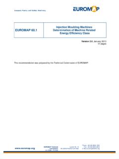
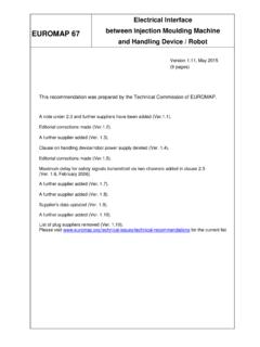
7 Standard frames (no extended frames). Setting of the CANopen device ID (two digits: 1 to 99) is done on the device, byselector switch or on a service panel, with the possibility of non volatile 66-1 General DescriptionVersion 66-1 Page 7 of Wiring CAN NetworkCAN devices are wired as a bus. They always feature two CAN connectors. The wiring is fromthe control to the first connector of the first device, then from the second connector to the nextdevice, and so on. The CAN bus must be terminated to avoid sketch below illustrates the wiring 1: CAN NetworkEUROMAP 66-1 General DescriptionVersion 66-1 Page 8 of EUROMAP 66 cableThe EUROMAP 66 cable is defined as follows:DSUB 9 connectorDSUB 9 connectorCAN HighCAN LowCAN Groundtwisted pairCAN shieldpin 5pin 7pin 2pin 3 ISO high speeddriverDCDCDC decouplinghigh speedoptocouplersCAN interface ofperipheral equipmentDSUB 9 connectormasterplasic processingmachineryslaveto nextperipheral equipmentEUROMAP 66 cablepin 5pin 7pin 2pin 3peripheralequipment(CAN 24V)pin 9pin 9optional+ 24 VCAN HighCAN LowCAN Groundtwisted pairCAN shieldpin 5pin 7pin 2pin 3pin 5pin 7pin 2pin 3(CAN 24V)pin 9pin 9+ 5 VFigure 2: EUROMAP 66 cableSee also Physical Basic aspectsIn principle CANopen EUROMAP devices must be implemented as per [DS-301].
8 Therequirements listed below form a subset of this General requirementsThe following general requirements apply: A CANopen EUROMAP device must support the requirements which apply to a Minimumcapability device as per [DS-301]. Master/slave: the machine (control) is CANopen master, the Peripheral device is slave. The COB IDs must be set by default as per Predefined Connection Set. Node guarding must be supported. The reaction to a Node-Guard-Event lies in thecompetence of the manufacturer of the device ( continue working with the last validnominal values or switch off). The Bootup Protocol has to be implemented. Object 1008h (manufacturer device name), 1009h (manufacturer hardware version) and100Ah (manufacturer software version) are mandatory. 1008h contains the manufacturerspecific device 66-1 General DescriptionVersion 66-1 Page 9 of 10 SDO must be acknowledged within 50 milliseconds.
9 SDO with invalid values (modes which are not supported, value outside tolerance, etc.) aregenerally to be acknowledged with Mandatory Objects for all EUROMAP 66 devicesObject at index 2000h describes type and version of the EUROMAP device. It is composed of a8-bit field which describes the EUROMAP code, and three 8-bit fields which gives informationabout the EUROMAP device profile. The device profile parameter is profile specific. Itsspecification does not fall within the scope of this document, it is defined in the appropriate DESCRIPTIONENTRY DESCRIPTIONA ccessroPDO MappingNoValue RangeUNSIGNED32 Default ValueNoMSBLSBP rofile VersionProfile IndexEUROMAP66-Profile CodeEUROMAP66 CodeEUROMAP66-Code: 66 (42h)Index2000hNameEUROMAP66_Device_Prof ileObject CodeVARData TypeUNSIGNED32 CategoryMandatoryEUROMAP 66-1 General DescriptionVersion 66-1 Page 10 of 10 EUROMAPE urop isches Komitee der Hersteller von Kunststoff- undGummimaschinenEuropean Committee of Machinery Manufacturers for thePlastics and Rubber IndustriesComit Europ en des Constructeurs de Machines pourPlastiques et CaoutchoucComitato Europeo Costruttori Macchine per Materie Plastiche eGommaSee you Copyright by EUROMAP