Transcription of PROTOCOL No. 10091001 Site Acceptance Test of
1 NOTE:THIS IS A REAL SAT PROCOL, BUT IN ORDER NOT TO DISLOSE CUSTOMER IDENTITY AND SYSTEM PARAMETERS, SOME DETAILS WERE ERASED AND PHOTOS WERE ALTEREDPROTOCOLNo. 10091001 Site Acceptance Test of SYSTEM FOR PREPARATIVELIQUID CHROMATOGRAPHYSEPARSYS TABLE OF CONTENTS1. INTRODUCTION2. APPROBATION3. PURPOSE4. SCOPE5. DESCRIPTION OF THE AND EVALUATION6. APPENDIXES1. INTRODUCTIONThe present Site Acceptance Test (SAT) PROTOCOL details the installation and operational test which must be successfully executed before the SEPASYS can be released for the use and describes test results of APPROBATIONThe approbation of the current SAT PROTOCOL is placed under the responsibility of Separlab : Stanislav Vozka, Managing Director 3.
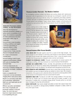
2 PURPOSEThe Site Acceptance Test (SAT), is a functional test of the preparative chromatographic system, including equipment, instruments and controls, and verifies of subsystems and whole unit are working SCOPEThis PROTOCOL is applied to SYSTEM FOR PREPARATIVE LIQUID CHROMATOGRAPHY SEPARSYS DESCRIPTION OF THE INSTALLATIONS eparsys is composed by: a 399 mm diameter stainless steel column PC 01 which has length 1100 mm and is eqiupped by an hydraulic oil cylinder having inner diameter 96 mm. and stroke 350 mm and is feeded by an oil manual pump with a manometer; the column is packed by sphjerical silica sorbent delivered by the customer spliting block for input of liquid to the column consisting of two T pieces, three high pressure ball valves and an electronic pressure sensor three piston membrane pumps Wanner G3 with frequency changers and connecting pipelines UV-VIS detector with remote cell which is connected by optical cables to monitor mobile phase composition computer unit with modified software ECOMAC to set system parameters and to monitor detector signals and pressure in the column.
3 PROCEDURE AND TESTSFor each type of test, a specific sheet is prepared. (starting from the annex 3 of the current PROTOCOL ). Each test sheet contains the test scope, the method, the Acceptance criteria, the equipment or instruments used to perform the test, the specific test results, the test comments, the test status, the signatories and the dates for the execution by the person who has performed the tests and the person who has controlled them. During the tests, record all the results are written with a blue ink in the corresponding fields of the sheet, under the expected values. According to the noted values correspond to the expected values, indicate the test status with the date and initials. All the appendices have to be clearly identified with the PROTOCOL number, the test number, the test date and the signature of the person who has performed the test.
4 For any correction, strike through with a unique line and add the initials and the date, with blue ink. Note the correct data. Date and sign the correction. If the result does not correspond to the expected and if the error cannot be resolved straight away, a deviation report should be DOCUMENTATIOND ocumentation delivered with instrument is listen in the Appendix 3. All items are to be found and Acceptance CRITERIAEach test sheet contains the Acceptance criteria to be RESULTS EVALUATIONAll tests were performed and all criteria were fulfilled. System is Teva Czech Industries .. Ing. Jaroslav Ry kFor Separlab .. RNDr.
5 Stanislav Vozka6. WHO HAVE PERFORMED THE OF EQUIPMENT COMPLETENESS ASSEMBLING AND HYDRAULIC SYSTEM PRESSURE PACKING OF THE WIRING AND SOFTWARE PUMPS INSTALLATION AND CONTROL DETECTOR INSTALLATION AND FUNCTION CONTROL SAMPLE INJECTION PERSONNEL WHO HAVE PERFORMED THE SAT To allow us to identify the people who have completed the Appendices of this PROTOCOL , these people must record their name and the name of the company which employs them in the table set out below (in capital letters) and place a specimen of their signatures and initials in the corresponding (INITIALS)Jaroslav Ry kTeva Czech Industry Investment manager JRPetr Havr nekSeparlab Technical directorPHMilos BorilSeparlab R&D ManagerJKStanislav VozkaSeparlab Managing LIST OF EQUIPMENT USEDEach equipment used to SAT tests must be listed in the table below, indicating, if applicable, the data concerning the calibration of this equipment.
6 Name of theequipmentModelSerial voltage and current measuring deviceSolid V12 manometer Bourdon typeHansa Flex O 630 250 bar130710calibrated manometer Bourdon typePower team0 700 bar4130568971calibrated with measuring rodmetal distances measuring Sony DSLR A 350 reservoirs 100 l volume, devided by each10 clockTimex DOCUMENTATIONTest title: Check of the documentationPurpose:This section verifies the presence and the organisation of the documentation according to the technical standard in force. Method:Verify that the documentation necessary for the validation, use and maintenance, andlisted below, has been that this documentation is organised in accordance with current technical :Not List of of items1 Construction and assembly plans od PC 01 column1 set2 Construction and assembly plans of electronic unit SEPAREL 011 set3 Certificates and documentation of materials of column and system parts1 set5 Electrical-connection diagrams and installation plans1 set6 Instruction manual delivered with the system1 pc7 Instruction manual for mobile phase pumps1 pc8 Instruction manual for UV detector 1 pc9 Instruction manual for hydraulic system1 pc10 Instruction manual for software1 pc11 Instruction manual for USB communication unit1 pcCriteria:The documents listed hereafter are present and organised according to the technical byJRSVDate: : DELIVERY COMPLETENESS TESTTest title.
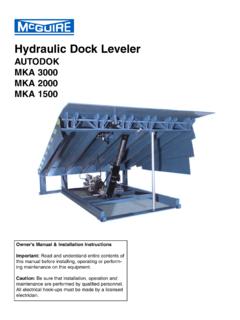
7 Delivery completeness testPurpose:This section details the tests which will be carried out to ensure that all components of the equipment were manufactured and delivered in accordance with packing list and production documentationMethod:1 Delivered assembled parts and subsystems were checked according packing list. 2 Parts and subsystem were unpacked and once more checked according production :Not All the components according packing list are All parts according production documentation are byJRSVDate: : PassedSignatures: COLUMN ASSEMBLING TESTTest title: COLUMN ASSEMBLING TESTP urpose:Demonstrate that all parts fit together, the column pistons are assembled well, hydraulic system is working, piston can be pressed to column tube, column stayin well on legs, all screws are free of : Assemble pistons with seals and supports and end fittings.
8 Assemble output flange with legs. Insert the tube to output piston unit and press piston inside tube using piston rods for upper flange. Assemble upper flange with hydraulic cylinder to the column upper flange by four thread rods with distance tubes. Insert next two rods with distance tubes. Insert upper piston unit on the plastic plate and connect it to hydraulic piston. Connect hydraulic pump to the cylinder. Remove plate and push the piston down by hydraulics. Check if piston is coming smoothly to the column tube. Check oil :DSL camera Sony A350 Record:Assembled piston unitColumn tube transportationColumn tube inserted to the bottom pistonColumn tube assembled to the bottom botton part assembledColumn upper flange assemblingUpper piston inserted into column tubeFully assembled upper column partCriteriaAssembling done without problems.
9 Column in function. ConformsYesChecked : COLUMN AND HYDRAULIC SYSTEM: PRESSURE TESTTest title: COLUMN AND HYDRAULIC SYSTEM: PRESSURE TESTP urpose:Demonstrate the column with hydraulic unit is able to work to its maximum pressure without leakage. Method: Close output column fitting. Fill full column with demineralized water (70 mm under the edge). Move upper piston inside the column till the time when only water without bubbles is flowing out of the column. Close input fitting. Start pressurize the hydraulic piston to produce 50 bar pressure. Check all possible oil and water following distances after each pressure increasing:a) between bottom column and piston flange on six different places equally distanced on the flanges to measure bottom bolts elongationb) measure bottom piston flange deformation according the drawing in two perpendicular directions near to the flange centrec) measure upper piston flange deformation according the drawing in two perpendicular directions near to the flange centreCheck oil and water leakages on all places, mainly on side of piston seals after each pressure increasingIncrease oil pressure in following steps.
10 100 bar, 200 bar, 300 bar, 400 bar, 470 bar, measure prescribed distances, check the leakage and increase the pressure afters 5 minutes. Release the oil pressure in hydraulic circuit then. Wait 120 min. Measure described distances again and compare with prescribed values in followed tables (record page): Deassemble the column and measure deflection of upper piston frit and upper piston support :Oil manometerLength measuring rodSmall distances measuring device ExtolRecord:Description 100 bar 200 bar 300 bar400 bar470 barmax. valueof elongationbottom column and piston flange, smallest - largest (mm)6,739,066,799,106,739,076,809,126,71 9,122,00% of the length, ,13 mm0,18 mmbottom piston flange defor-mation (mm)nono111,51,5221 % of the diameter mmupper piston flange defor-mation (mm)nononono0,50,51 % of the diameter ,8 mmNo leakage of both oil and water was frit deformation was of piston support was 5 mm.