Transcription of PUMP PERFORMANCE MEASUREMENTS Jacques …
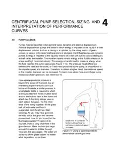
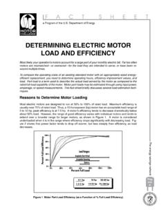
1 PUMP PERFORMANCE MEASUREMENTS Jacques chaurette p. eng. April 2003 Synopsis This article examines how to take flow and pressure measurement and then calculate the total head of a pump based on these MEASUREMENTS . How to do motor power MEASUREMENTS and where to get the data required on the motor such as efficiency and power factor typical induction motors. What is power factor anyway? Find out here. Make sure that the actual pump speed matches the speed of the pump s characteristic curve to avoid errors. And finally, some advice on what to expect from the results of PERFORMANCE tests. To verify if the pump is performing properly or establish if we have the right pump for the job we need to do two things : measure the pressure before and after the pump and measure the flow rate though the pump. The first is easy to do, the second not so easy without a reliable flow meter. We will use as an example an Ahlstrom APT55-8 pump with an open impeller (560 mm dia.) running at 1180 rpm (see Figure 1).
2 2 To calculate the total head of the pump, we need to measure the pressure before and after the pump as well as compensate for the pressure gauge elevation with respect to the pump centerline and the velocities of the fluid before and after the pump. Why? First of all this is the standardized method that is used by all North-American pump manufacturers and is stipulated by The Hydraulic Institute ( ). Secondly it just makes good sense. We need to compensate for the pressure gauge elevation since if we position our gauge at different heights with respect to the pump centerline we will get a lower reading. This is normal since pressure is affected by elevation. The energy produced by the pump is the total energy present at the outlet minus the energy present at the inlet. Instead of energy in pump systems it is preferable to use specific energy which is energy per weight of fluid displaced or head. Therefore the definition we will use is: the total head of the pump is the difference between the specific energy or head at the outlet minus the specific energy or head at the inlet.
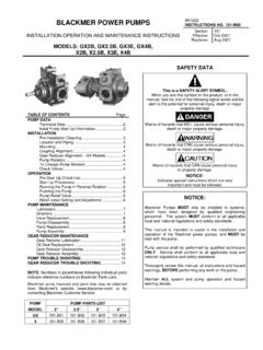
3 Figure 1 Characteristic curve for an Ahlstrom APT55-8 centrifugal open impeller pump at 1180 rpm. 3 The head at the outlet is composed of three quantities: elevation head, velocity head and pressure head. This can be expressed wit equations [1] and [2]: The head at the discharge is: SGpsigpsftgsftvftzfluidftHDDDD)( )/(2)/()()(222 ++= [1] The head at the inlet is: SGpsigpsftgsftvftzfluidftHSSSS)( )/(2)/()()(222 ++= [2] The total head is the difference between the head at the discharge minus the head at the suction. SGppgvvzzHHfluidftHSDSDSDSDP)( )()(22 + + == = [3] The reference for the elevation zD and zS is taken with respect to the pump centerline as stipulated by the Hydraulic Institute (see Figure 2). The pumps usually have different inlet and outlet connection sizes and therefore the difference in velocity head will compensate for that. This method will ensure that you get the same results as the pump manufacturers. We cannot always have our pressure gauges installed at our preferred locations.
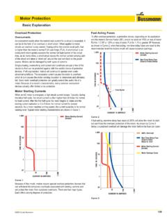
4 If the pressure gauge at the outlet of the pump is installed after a check valve for example, you must add the value of pressure head loss of this valve to the total head of the pump to account for its effect on the total head. You will have to do a calculation of this pressure head loss based on information supplied by the manufacturer. 4 Let s do an example with some tests results that I gathered recently. The pressure measured at the discharge gauge was 74 psi, there was no flow meter available and the flow rate is assumed to be 2200 gpm, this flow is the flow that corresponds to the position of the operating point on the characteristic curve of the pump (see Figure 1). We will have to check the flow rate with some other method. The discharge gauge is 5 feet above the pump centerline and the suction gauge is 1 foot. The velocity is given by: 22)(min)/.( )/(inDUSgalqsftv= [4] The velocity at the discharge is: )/(2==sftvD [5] The velocity at the suction is: )/(2==sftvS [6] The total head is then: Figure 2 Location of pressure gauges when doing total head MEASUREMENTS .
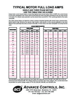
5 5 1771)(0)( ) ( )(22= + + = psigpsigfluidftHP [7] Pump power consumed Assuming that our assumption for the flow is correct and is 2200 gpm which is the flow predicted by the pump curve (see Figure 1), we can calculate the power consumed by the pump with equation [8]. pumpPUSgalqfluidftHSGhpP =3960min)/()()( [8] The specific gravity SG is one (1). The total head measured was 177 ft and the flow is 2200 gpm. The efficiency of the pump is given by the characteristic curve (see Figure 1) and is )(= =hpP [9] Motor power MEASUREMENTS Motor power consumption can be calculated if we know how much current is used. The formula is: ..)()( )(FPampIvoltVhppmotormotor = [10] V is the voltage supplied to the motor, usually 575 or 2300 volts. I is the current in amps consumed. The efficiency of the motor is motor and is supplied by the motor manufacturer. is the power factor of the motor and it s value must also be supplied by the manufacturer. The efficiency and power factor information is available on the motor nameplate but it is only valid for operation of the motor at full load, both these values drop when the motor operates at less than full load.
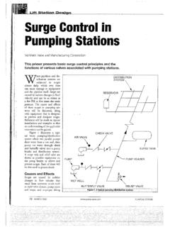
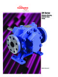
6 The manufacturer can also provide this information for various motor loads. If this is not feasible, you can download a database from the Department of Energy in the United States Which contains information from many major manufacturers for all sizes of motors and loads. If this fails, or is not available to you, you can use the following charts which are based on tests done with motors of various manufacturers and sizes. 6 Figure 3 Efficiency values for various motors sizes and loads (source: Determining Electric Motor Load and Efficiency by the US Department of Energy, , click pumps , click, Energy and LLC, click DOE resources). Figure 4 Power factor values for various motors sizes and loads (source: Determining Electric Motor Load and Efficiency by the US Department of Energy, , click pumps , click, Energy and LLC, click DOE resources). 7 Note: The values of efficiency given in Figure 3 are percent of the efficiency at full load, this is not the absolute efficiency.
7 If a kiloWatt meter is available and we take a measurement on one phase lead of the motor, then we don t need to know the power factor of the motor but only the efficiency. The power consumed by the motor will be given by: motormeasuredmotorkWPhpp =)( )( [11] To determine the loading of the motor we need the ratio of the amps consumed to the nameplate amps. However the loading will also vary depending on the supply voltage, supply voltage is not always exactly equal to the nameplate voltage. Therefore the load on the motor is: nameplatemeasurednameplateloadfullmeasur edVVII loadMotor = [12] The motor is manufactured by General Electric, 250hp, 2300 volts, 58 full load amps. The amps measured were 34 amps. The voltage supplied to the motor is 2300 volts. The operating load is then: =loadMotor [13] The motor operating load is 59%. Based on this motor load, the information from the manufacturer gives us for the efficiency and for the power factor. Therefore the power consumed by the motor using equation [10] is: )(= =hppmotor [14] The power provided by the motor to the pump is 143 hp and is very close to the power consumed by the pump which was provided by the data on the pump curve and the pressure MEASUREMENTS (143 hp)as calculated in equation [9].
8 This means that the pump is operating as expected according to the manufacturer s tests. 8 Motor speed Motor speed varies with load. The synchronous speed of an AC induction motor varies with the number pf poles. A 4 pole motor has a synchronous speed of 1800 rpm. The full load rpm of the motor will be indicated on the nameplate. In the example of the motor mentioned previously, the full-load rpm is 1780. If the motor were operating at half load, the speed would likely be approximately 1790. This has two effects on your pump PERFORMANCE MEASUREMENTS : 1. The pump manufacturer s curves will be determined for the full load rpm of the corresponding synchronous speed of the motor, in the case of this motor it is 1780 rpm. Not al the pump manufacturers use the same full load speed. If the motor is running at half load then the speed will be a little higher (1790 rpm) and this will throw off your calculations when comparing your motor power MEASUREMENTS with the pump curve.
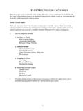
9 2. The pump power consumed varies with the rpm cubed, so that a small change in rpm will greatly affect the power calculation. See the Affinity laws in the Cameron Hydraulic data book (Appendix B). If you don t know what speed the motor is running at, it can easily be measured with a strobe light which is usually readily available in maintenance departments. Figure 5 shows the result of operating a pump at a higher speed than the initial speed for which the characteristic curve was established. Since the head varies with the square of the speed small differences in speed can be significant. Figure 5 The effect of speed on total head. 9 Flow MEASUREMENTS The measurement of flow rate is not always an easy task. Rarely, is there an accurate flow measurement device on the pipe which we are interested in. It is sometimes possible (without incurring a great expense) to measure flow by measuring the rate at which the discharge reservoir is filled, or a suction tank is emptied.
10 The measurement volume, or the time of the measurement , should be small to avoid influencing the total head of the pump and therefore causing flow variations. There are portable non-invasive flow measuring instruments that are available. One works on the Doppler principle and works better with fluids that have suspended particles. My experience with the Doppler measuring instrument has not been good, I have found that the location of the sensors is critical. The other type of and portable non-invasive flow measuring instruments is called the Transit time. This instrument works best on fluids with little or no suspended particles. A final word of caution. Any MEASUREMENTS deduced from data extracted from the pump curve assume that the pump is in good working condition (for example, proper clearance between impeller and casing, no excessive wear, etc.). This is of course not always the case. Don Casada has written many articles which are posted on the web which covers some of the same territory as this article, I heartily recommend them see A few tips on using measurement and diagnosing pump Problems With a few simple MEASUREMENTS of pressure and flow, we can diagnose pump problems and plan preventative maintenance on pumps .