Transcription of Push- Pull Ventilation I Design
1 'f !.,,' I la , / /. Push- pull Ventilation cyin Process Design By Kevin D. Bomboy, /- 24//6. f2F. Energy-efficient Design has been emphasized for process and buirCring systems f o r many years. When the Department of Energy (DOE). assigned STV Group, Ponstown, PA, to a plating facility Design project, energy conservation was a main objective of the Design team. In this Liquid surface application, the primary means of reducing energy use was by decreas- ing the Ventilation air requirements of the plating tanks. The objective was achieved through a modified Push- pull Ventilation system, a form of tank coverlair limiting device. The Pressure slot energy reduction lowered operating t J- tank _f - costs ai the faciliry by 77percent. T" e DOE required a new electro- plating and technology support facility to replace a 30-year-old, antiquated plant.
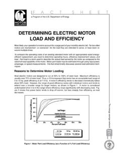
2 A state-of-the-art facility was required to meet DOES. __. ig. I-Standard Push- pull ventilotlon system captured in the exhaust system and * The system is simple with no plating and deplating needs with removed by water scrubbers prior to moving parts. precision. the air being discharged into the Through intensive studies, the atmosphere (Fig. 2 and 3). Despite its advantages, there are Design team determined that two This system typically operates aspects of a conventional Push- pull features were necessary to meet continuously, pulling a large quantity Ventilation system that the Design DOE'S goals: of conditioned air from the building. team felt were undesirable for a For the DOE building, a full Push- pull modified Push- pull system. 1. Theuse of an automated plating Ventilation system would exhaust line where the precision required about 100-150 ft' of air per min from * High energy use through tank for the parts plating is controlled every ft2 of plating tank for a building Ventilation air.
3 Automatically and not subject to total of 100,000 ft3/min. Operating the * The possibility of chemicals from human error (also providing a system would cost DOE an estimated one tank dripping into the other vehicle to operate the modified $159,185 per year. tanks during transfer of parts along Push- pull system). Despite its high energy usage, a the plating line. 2. An exhaust system that will conventional Push- pull Ventilation High energy use for heating the decrease energy use. system has several desirable aspects plating tanks. that are incorporated into the modified Rapid evaporation of some chemi- Full Push- pull - Push- pull system: cals from uncovered tanks. The Conventional System Greater possibility for operating Uncovered plating tanks have been The system has maximum flexibil- personnel coming in contact with the industry standard.
4 The tanks ity with no obstructions over the the chemicals in the tanks. remain open with operator protection provided by either an exhaust, or combination supply-exhaust ( push - - tank. The operator can easily see the tank contents. The Modifled Push- pull System The Design strategy was to develop a pull ), Ventilation system (Fig. 1). This * The system provides the maximum modified Push- pull system that creates a curtain of air across the tank operating protection from plating provides the operator the safety and tops, which prevents contaminants fumes. visibility of a full Push- pull system from escaping. Contaminants are during plating, but reduces energy 44 PLATING 8 SURFACE FINISHING. 1 Society in 1964 as a member of the Studied the effect of high-speed AESF Activities Saginaw Valley Branch. He became solution flow on the product and Jim is an active participant in the iffiliated with the Detroit Branch in economics of copper electrowin- Society, and has held numerous 1977, served on the Branch Board of Managers, and was Branch president from 1985-86.
5 In addition, Jim - ning. Early work involving the use of nickel underlayers in nickel-black positions within his various Branch affiliations over the years. His 1995- 1996 AESF responsibilities included: continues to be active on the national chromium systems for solar level, serving on AESF's Research Board, the Technical Education Board energy applications. Developed an alternative to the chemical preplate process for - * Publications Board ResearchBoard, ex-officio member t'continuous Steel Strip Plating plated plastics, based on vacuum /' Committee, advisor technology-philosophy involved *Meeting&and Symposia Committee the best of both vacuum and /' . -Technical Specialist Contributing- Technical Editor, I. the Society's P&SF. Delegate, Detroit Branch He is also a member of the Ameri- I. :an Society for Metals, and is a past member of the Society of Vacuum Interaction Between \ loaters and the Electrochemical Electrogalvanized Zinc Deposit \, Society.
6 Honorary society member- Structure and the Forming Properties rhips include Sigma Xi and Alpha of Sheet Steel. Tau Iota. a comprehensive study Although quiet and soft-spoken, Summary of Accomplishments lim has a solid reputation for his In addition to holding five U S . cnowledge of the finishing industry patents, Dr. Lindsay's many industry- and plating systems. His love of related accomplishments include: iaveling has made him a willing and :xcellent ambassador for GM, the * Graduate work shed light on the inisbing industry and the AESF all. effect of hydrogen evolution on wer the U S . , Japan and Australia. cobalt-important information rhis abbreviated look at the 1996. during the nickel shortage of the Scientific Achievement Award early 1970s, when cobalt was .ecipient's accomplishments illus- touted as a substitute for nickel i rates why he is a definite stand-out in he.
7 Industry. Congratulations, Dr. * Developed proprietary p cessey >mdsay! PBSF. \ . tron for wear- and friction-redu coatings in various automotiv2, ., bearings. applications. /. OOPS! i . We left out an author's bio. In a feature about electroplated metallic glasses by John Donaldson, appearing on page 16 of the July 1996 issue of Plating and Surface Finishing, we inadvertently omitted information about the author. After having this pointed out by a couple of readers, here is the scoop on the author: John Donaldson has 40 years' experience in electroplating management and engineering. He has worked as a consultant since 1986, specializing in plant and equipment Design ; plating for electronics and precious metals conservation; trouble shooting; and process and product development. Donaldson is the author of more than 40 papers for various technical publications, and served as a feature editor for Plating and Surface Finishing and Metal Finishing magazines.
8 He was a contributing author for the Metal Finishing Guidebook, the Electroless Plating Manual, and the AESF Illustrated Lecture Series. Donaldson is a Past National President and Honorary Member of the AESF. September 1996 43. OOlleniO". Fig. 3- pull side baffle that reduces allflow operates on the Same shaft that Opens and closes Fig. 2-Tvpical plating exhaust system. the lid cover of the plating tank. consumption during periods when * All lids are automatically controlled consumption was reduced because of tanks are empty. The team developed to prevent operators from leaving the lower airflow quantity. Capital a covered tank system than can be lids open or opening too many lids outlay was decreased because the new opened during plating and closed at one time. system allows a reduction in the size during idle periods.
9 The automated Airflow velocities in exhaust and of support equipment, such as hoist and computer system activates supply duct mains should be kept at ductwork air handlers and scrubbers. the opening and closing of covers so the lower suggested boundary to A simple payback of less than six that only two tank lids per plating line minimize fluctuations of airflow months was calculated for the DOE. can he open simultaneously-the tank with the opening and closing of project. The estimated capital cost of from which the part is being removed and the tank the part will enter next. Airflow from the plating tanks is - lids. Baffles for push and pull air slots are adjustable to fine-tune the air the conventional Push- pull system is $450,100, while the modified push - pull was estimated to cost $488,620. reduced when the tank is covered.
10 Quantities and flow characteristics The difference in capital costs- A cover was developed that utilizes of the system. $38,520-divided by the difference in - the tank lid as an air-limiting device. 0 Either a variable volume exhaust operational costs-$1 19,390-results Baffles affixed to the lid partially fan or a bypass damper will be used in a simple payback of years. block the pull and completely block to account for the varying airflows The energy savings outweighs the the push duct openings serving the caused by lids opening and closing. additional capital cost of the modified tank's Ventilation system (Fig. 3). 0 All materials used in the modified Push- pull system. When the lid is closed, a reduced air Push- pull Design must resist The modified Push- pull system flow occurs, but it still holds the tank corrosion from the specific chemi- slightly restricts the operator, but at a negative pressure, preventing cals in the tanks.


![ADA Compliance Checklist Guidance [APS] (Accessible ...](/cache/preview/5/c/4/b/f/1/b/5/thumb-5c4bf1b5b7dbcfe1843c76286083789d.jpg)