Transcription of PVG 32 Proportional Valves Service Parts Manual
1 PVG 32. Proportional Valves Service Parts Manual PVG 32 Proportional Valve Service Parts Manual Survey SURVEY Page Sectional drawing .. 3. Identification and 4. Spare Pos. 1: PVP - Pump side module .. 24. PVPV/M - Pump side module .. 28. Pos. 2 : PVB - Basic module .. 30. Pos. 3: PVLA - Anti-cavitation valve .. 32. Pos. 4: PVLP - Shock and anti-cavitation 32. Pos. 5: PVS/PVSI - End 34. Pos. 6: PVAS - Assemply kit, 36. PVAS - Assemply kit, 38. Pos. 7: PVPX - LS-unloading valve .. 40. Pos. 8: PVPC - Plug for external pilot 40. Pos. 9: PVBS - Main 42. Pos. 10: PVM - Mechanical activation .. 44. Pos. 11: PVMF - Cover for friction detent PVMR or for float position .. 46. Pos. 12: PVH - Cover for hydraulic 46. Pos. 13: PVMD - Cover for machanical 46.
2 Pos. 14: PVEO - Electrical activation .. 48. Pos 15: PVEM - Electrical 48. Pos. 16: PVEH/PVES - Electrical 49. Set of seal sets PVG 32 .. 50. 2001 Sauer-Danfoss Sauer-Danfoss can accept no responsibility for possible errors in catalogues, brochures and other printed material. Sauer -Danfoss reserves the right to alter its products without prior notice. This also applies to products already ordered provided that such alterations can be made without subsequent changes being necessary in specifications already agreed. All trademarks in this material are properties of the respective companies. Sauer-Danfoss and the Sauer-Danfoss logotype are trademarks of the Sauer-Danfoss Group. All rights reserved. Frontpage: , , , , Drawing 2 520L0211.
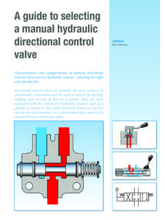
3 PVG 32 Proportional Valve Service Parts Manual Sectional drawing PVG 32 1. Pressure relief valve 11. Main spool SECTIONAL DRAWING 2. Pressure reduction valve for pilot 12. LS-pressure relief valve supply 13. Shock and suction valve, PVLP. 3. Pressure gauge connection 14. Pressure compensator 4. Plug, open center 15. LS-connection, port A. 5. Orifice, closed center 16. LS-connection, port B. 6. Pressure adjustment spool 17. Anti cavitation valve, PVLA. 7. Plug, closed center 18. Load drop check valve 8. LS-connection 19. Pilot supply for PVE. 9. LS-signal 20. Max. oil flow adjustment screws for 10. Shuttle valve port A and B. COST-FREE REPAIRS We would point out that cost-free repairs as mentioned in Sauer-Danfoss General Conditions of Sale, are carried out only at Sauer-Danfoss or at Service shops authorized by Sauer-Danfoss.
4 520L0211 3. PVG 32 Proportional Valve Service Parts Manual Identification STANDARD 01 3 A 0 0299. INSTALLATION: Week of manufacture PVM TO THE RIGHT Year of manufacture OF PVP Day of the week (A = Monday, B = Tuesday ..). Issue number Series number C: PVG-Number, week and year of installation D: PVP-pressure setting E: PVP-Number, Week , year and day manufacturing, issue and series No. F: PVB-A-Port, Number, Week , year and day manufacturing, issue and series No. 4 520L0211. PVG 32 Proportional Valve Service Parts Manual Installation INSTALLATION AND PLUG Modul of PVB 1 2 3 4 5 6 7 8 9 10. ORIENTATION L mm 82 130 178 226 274 322 370 418 466 514. L in * Room for dismantling 520L0211 5. PVG 32 Proportional Valve Service Parts Manual Installation STANDARD, OIL FLOW DIRECTION.
5 AND SETTING OF MAX. FLOW. PVM TO THE RIGTH OF. PVP. 6 520L0211. PVG 32 Proportional Valve Service Parts Manual Installation STANDARD, Electrical connection OIL FLOW DIRECTION. AND SETTING OF MAX. Proportional activation FLOW UDC 11 - 15 V __. 22 - 30 V __.. Pin 1 (U+) 2 (US) 1 (U+) 2 (US). PVM TO THE RIGTH OF Q: P A UDC ( ) UDC UDC ( ) UDC. PVP Q: P B UDC ( ) UDC UDC ( ) UDC. Neutral UDC UDC UDC UDC. On/off activation UDC 11 - 15 V __. 22 - 30 V __.. Pin 1 2 1 2. Q: P A UDC 0 UDC 0. Q: P B UDC UDC UDC (UDC. Neutral 0 0 0 0. 25 Pin SUB-D connector with M3 screws (MIL-DTL-24308). F: Branch circuit for fault indication E: Emergency circuit braker 520L0211 7. PVG 32 Proportional Valve Service Parts Manual Installation OPTION, OIL FLOW DIRECTION.)
6 AND SETTING OF MAX. FLOW. PVM TO THE LEFT OF PVP. 8 520L0211. PVG 32 Proportional Valve Service Parts Manual Installation OPTION, Electrical connection OIL FLOW DIRECTION. AND SETTING OF MAX Proportional activation FLOW UDC 11 - 15 V __. 22 - 30 V __.. Pin 1 (U+) 2 (US) 1 (U+) 2 (US). PVM TO THE LEFT OF PVP Q: P A UDC ( ) UDC UDC ( ) UDC. Q: P B UDC ( ) UDC UDC ( ) UDC. Neutral UDC UDC UDC UDC. On/off activation UDC 11 - 15 V __. 22 - 30 V __.. Pin 1 2 1 2. Q: P A UDC 0 UDC 0. Q: P B UDC UDC UDC (UDC. Neutral 0 0 0 0. 25 Pin SUB-D connector with M3 screws (MIL-DTL-24308). F: Branch circuit for fault indication E: Emergency circuit braker 520L0211 9. PVG 32 Proportional Valve Service Parts Manual Installation CONNECTIONS, PUMP SIDE MODULE, PVP.)
7 Connection Max. tightening torque P A/B T LS, M, LSA, LSB, LX. PVH, Accumulator PVS PVSI. Screwed connection G 1 2 G 3 4 G 1 2 G 3 4 G 1 4 G 1 8 G 1 4. 130 Nm 210 Nm 130 Nm 210 Nm 40 Nm 17 Nm 40 Nm With steel washer (1150 lbf in) (1850 lbf in) (1150 lbf in) (1850 lbf in) (350 lbf in) (150 lbf in) (350 lbf in). 30 Nm 50 Nm 30 Nm 50 Nm 20 Nm 15 Nm 20 Nm With cooper washer (270 lbf in) (445 lbf in) (270 lbf in) (445 lbf in) (180 lbf in) (135 lbf in) (180 lbf in). With aluminium 70 Nm 110 Nm 70 Nm 110 Nm 30 Nm 15 Nm 30 Nm washer (620 lbf in) (970 lbf in) (620 lbf in) (970 lbf in) (270 lbf in) (135 lbf in) (270 lbf in). 130 Nm 210 Nm 130 Nm 210 Nm 40 Nm 17 Nm 40 Nm With cutting edge (1150 lbf in) (1850 lbf in) (1150 lbf in) (1850 lbf in) (350 lbf in) (150 lbf in) (350 lbf in).
8 7 11 7 11 1 3 1. Screwed connection UNF 8 in-14 16 in-12 8 in-14 16 in-12 2 in-20 8 in-24 2 in-20. 90 Nm 120 Nm 90 Nm 120 Nm 30 Nm 10 Nm 30 Nm O-ring (800 in-lbs) (1060 in-lbs) (800 in-lbs) (1060 in-lbs) (270 in-lbs) (90 in-lbs) (270 in-lbs). 10 520L0211. PVG 32 Proportional Valve Service Parts Manual Installation INSTALLATION OF LEVER Screw the lever completely home Base with an angle of Base with an angle of . PRESSURE SETTING. PVP, LSA, LSB. 520L0211 11. PVG 32 Proportional Valve Service Parts Manual Installation PVE FAULT MONITORING Normal Green A: External relay B: Solenoid valve Fault Red A: External relay B: Solenoid valve 12 520L0211. PVG 32 Proportional Valve Service Parts Manual Installation PVE FAULT MONITORING Reaction time Fault Active fault monitoring Passiv fault monitoring BLOCK DIAGRAM Active Passive (a): Cut-off of solenoid Valves (a): Does not exist (b): Control signal for LED (b): Control signal for LED.
9 (c): Control signal for alarm output (c): Control signal for alarm output 520L0211 13. PVG 32 Proportional Valve Service Parts Manual Installation PVEH / PVEM / PVES Check max. lever travel in neutral position 1. Make sure the system is supplied with hydraulic power ADJUSTMENT OF PVE 2. Connect supply voltage (UDC) (Signal voltage = 0,5 UDC), or cut off the signal voltage WHEN MAX. LEVER (US) on pin 2. TRAVEL IS EXCEEDED. (PVE IS FACTORY- PRESET). Lever travel exceeded in PVG 32 Direction of rotation for adjustment of position transducer Direction A. Direction B. Turn of transducer Movement of lever 1. 4 mm [ in]. 1. 2 mm [ in]. 3. 4 4. 5 mm [ in]. 14 520L0211. PVG 32 Proportional Valve Service Parts Manual Installation EX INSTALLATION PVEH PVEO.
10 INSTALLATION OF PVE PVEH/PVES. PVEM. PVEO. 520L0211 15. PVG 32 Proportional Valve Service Parts Manual Installation BLEEDING (If the group is installed vertically, it is recommended to bleed it at the adjusting screws A). * Room for dismantling 16 520L0211. PVG 32 Proportional Valve Service Parts Manual Installation INSTALLATION. AND TECHNICAL DATA. FOR PVPX. Position Across flats Max. tightening torque 24 mm 45 Nm 1. [ in] [400 lbf in]. Max. operation pressure 350 bar [5076 bar]. Max. coil surface temperature 155 C [311 F]. Rated voltage 12 V __. 24 V __.. 22 C (71,6 F) coil temperature A A. Current consumtion 110 C (230 F) coil temperature A A. 22 C (71,6 F) coil temperature 19 W 19 W. Power consumtion 110 C (230 F) coil temperature 12 W 12 W.