Transcription of PVS Series Variable Volume 3/rev A Piston Pumps Suction ...
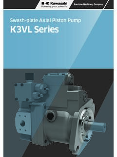
1 A-3 ABCDEFGHIJKLMNOP iston PumpsPVS SERIESVARIABLE Volume Piston PUMP0M**DischargeportSuctionportDrainpor tPVS Series Variable Volume Piston to Design No. 30 is applied on PVS-0B to make the pump more compact and lighter, and reduce noise. Production of PVS-3B has been discontinued. Use PZS-3B. Pressure adjustment 3 type has been added to PVS-1B-22 and PVS-2B-45. (Design No. 20 is applied only on PVS-2B-45*3.)FeaturesSpecificationsModel Volume at no-load /minPressureadjustment rangeMPa{kgf/cm2}PermittedpeakpressureMP a{kgf/cm2}Rotating speed *0-30 1 2 ( to ) to { to }2 to 7 { to }3 to 14 { to 143 }3 to 21 { to 214 }25{255} -1B -16*0 - (*) -12 1 2 ( to ) to { to }2 to 7 { to }3 to 14 { to 143 }3 to 21 { to 214 }25{255} -1B -22*0 - (*) -12 1 2 ( to ) to { to }2 to 7 { to }3 to 14 { to 143 }3 to 21 { to 214 }25{255} *0-(*)-12 1 2 ( to )
2 To { to }2 to 7 { to }3 to 14 { to 143 }3 to 21 { to 214 }25{255}500200021 PVS-2B-45*0-(*)-12 1 2 3-(*) ( to ) 7. to { to }2 to 7 { to }3 to 14 { to 143 }3 to 21 { to 214 }25{255}500200021 Note) Direction of rotation is clockwise when viewed from the shaft end. Handling Cautions during Pump Installation and Pipingz Use flexible couplings for connecting the pump shaft to the drive shaft, and prevent a radial or thrust load from be-ing applied on the pump For centering of the pump shaft, limit the eccentricity between the drive shaft and hydraulic pump shaft to mm, and keep the angle error within 1 .c Set the length of insertion between cou-pling and hydraulic pump shafts so that it is within at least 2/3 or more of the coupling Use a sufficiently rigid pump mounting Set the pressure on the pump Suction side to MPa or more ( Suction port flow velocity within 2 m/sec).
3 N Raise part of the drain piping to above the topmost part of the pump body, and insert the return section of the drain piping into the hydraulic fluid. Also, ob-serve the values in the following table to limit the drain back pressure to joint size 3/8" or more 1/2" or morePipe dia ormore 12 dia ormorePipe length1m or less1m or lessm Mount the pump so the pump shaft is oriented horizontally. Management of Hydraulic Operat-ing Fluidz Use good-quality hydraulic operating fluid, and use within a kinematic viscos-ity range of 20 to 200 mm2/sec during operation. Use an R&O type and an-ti-wear hydraulic fluid of ISO-VG32 to 68. The optimum kinematic viscosity during operation is 20 to 50 mm2 The operating temperature range is 5 to 60 C. When the oil temperature at start-up is 5 C or less, warm up the hydraulic pump by low-pressure, low-operation speed operation until the oil tempera-ture reaches 5 C.
4 C Provide a Suction strainer with a filter-ing grade of about 100 m (150 mesh). Besure to provide a return line filter of grade 20 m or less on the return line to the tank. (When the hydraulic pump is used at ahigh pressure of 14 MPa or more, we recommend providing a filter of 10 m or Manage the hydraulic operating fluid so that contamination is maintained at class NAS10 or Use hydraulic operating fluid within an operating ambient temperature of 0 to 60 C.(continued on following page)Energy-saving Type with Drastically Reduced LossA NACHI-proprietary semi-circular bar-rel swash plate that receives pressure on its surface ensures a stable dis-charge Volume at all times. This elimi-nates excessdischarge Volume , and enables the ef-fective use of power corresponding to the load "energy-saving type" conserves energy, reduces power loss, and helps to reduce hydraulic Type That Demon-strates Its Power QuietlyProprietary low-noise mechanisms are incorporated on the shoe, swash plate , valve plate , and other locations to en-sure silent operation.)
5 In particular, a semi-circular barrel swash plate stabi-lizes operation characteristics to ensure silent Pumps Inverter Drive Precautionsz Set the revolution speed within the range of the pump specification revolu-tion Changing the revolution speed may also affect the pump performance using the inverter, check if the pressure and motor load factor are within the range of use. Cautions at Startupz Before you start pump operation, fill the pump body with clean hydraulic fluid via the lubrication No. Injection amount cm3 PVS-0B-8220 PVS-1B-16, 22300 PVS-2B-35, 45650x An unload is required when the motor is started under condition . Consult your agent regarding the Make sure that the pump operates in the direction of rotation the same as that indicated by the arrow on the pump Air entering to the pump or pipes may cause noise or vibration.
6 At startup, set the pump discharge side to a no-load state, and operate the pump in the inch-ing mode to release any air in the pump or Provide an air bleed valve in circuits where it is difficult to release air at start-up. (See "IP Pumps " on page C -13.) How to Set Pressure and Discharge Volume For the factory default pump discharge Volume is set to "maximum" and dis-charge pressure is set to "minimum". Change the discharge Volume and dis-charge pressure settings according to your particular operating conditions.[Pressure adjustment]Turning the pres-sure adjusting screw CW increas-es the pressure.[Discharge Volume adjustment]Turning the flow rate adjusting screw CW decreases the discharge ) For details regarding the relationship between flow rate adjustment length and pump capac-ity q, see the tables provided in the installation dimension drawings for each of the Pumps .
7 Firmly tighten the lock nuts after you have fin-ished adjustments.[Note] Variable control mechanism Standard type N* : Pressure compensation type (manual mode) Option type P* : Pressure compensation type (re-mote control mode) N*Q* : 2-pressure, 2-flow rate control R*AS * : Solenoid cutoff control W*AS * : 2-pressure control RQ*AS * : 2-pressure, 2-flow rate control w/ solenoid cutoff C*AS * : 2-cutoff controlExplanation of model No. * : Pressure adjustment range 0 : 2 to { to } 1 : 2 to 7 MPa { to } 2 : 3 to 14 MPa { to 143kgf/cm2} 3 : 3 to 21 MPa { to 214kgf/cm2} * : Applicable to solenoid specifications A, S A * : SA-G01 S * : SS-G01 1 : 100V 50/60Hz 2 : 200V 50/60Hz 3 : DC12V 4 : DC24 VPVS 1 B 16 N 2 (*) 12 Design No.
8 30: PVS-0* 12: PVS-1*, PVS-2* 20: PVS-2*-45N3 onlyAuxiliary symbol None: Side port type Z: Axial port type (PVS-1*, PVS-2*)Pressure adjustment range [Note] ReferenceVariable control mechanism [Note] ReferenceMax. pump capacity (cm3/rev) Nominal 8, 16, 22, 35, 45 Mounting method B: Mounting flange type A: Mounting foot typePump size 0, 1, 2 PVS Series Variable Piston pump NQ, RS, WS, RQS and CS types are not available for the PVS-0B-8. NQ, RQS and CS types are not available for the PVS-1B-1622-Z and rangeDischargevolumeDischargevolumeDisch arge volumeadjustment rangeCCWCWP ressurePressureN2:3-14 MPaDischarge volumeDischarge volumeDischarge volumeDischarge volumeDischarge volumeDischarge volumeDischarge volumeP2:3-14 MPaP2:3-14 MPasol"ON"sol"OFF"W2:3-14 MPasol"ON"sol"OFF"N2:3-14 MPaQ1:2-7 MPaDischarge pressureR2:3-14 MPasol"ON"sol"OFF"Discharge pressureDischarge pressureDischarge pressureDischarge pressureDischarge pressureC2:3-14 MPasol"ON"sol"OFF"Discharge pressure[Example 1]N*: Pressure compensation type (manual mode)PVS -1B -16N2[Example 4]R*S*: Solenoid cutoff controlPVS -1B -16R 2S2 Solenoid specifications200V 50/60 HzSS-G01[Example 7]C*S*: 2-cutoff controlPVS -1B -16C2S2 Solenoid specifications200V 50/60 HzSS-G01[Example 2]P*.
9 Pressure compensation type (remote control mode)PVS -1B -16P2[Example 5]W*S*: 2-pressure controlPVS -1B -16W2S1 Solenoid specifications100V 50/60 HzSS-G01[Example 3]N*Q*: 2-pressure, 2-flow rate controlPVS -1B -16N2Q1[Example 6]RQ*S*: 2-pressure, 2-flow rate control w/ solenoid cutoffPVS -1B -16RQ2S1 Solenoid specifications100V 50/60 HzSS-G01A-5 ABCDEFGHIJKLMNOP iston PumpsNACHID rain portPressureadjusting screwFlow rateadjusting screwDischarge volumeDischarge pressure0M**SuctionportDrainportDischarg e portVariable Control MechanismsStandard typeOption typeSymbolExternal ViewCharacteristicsHydraulic CircuitExplanationNPressure compensation type(manual system)When the discharge pressure reaches the preset pressure set by the pressure compen-sator, the discharge rate is au-tomatically reduced to hold the pressure at the set pressure (full cutoff pressure).
10 PPressure compensation type(remote control mode)This mode demonstrates the same characteristics as the manual full cutoff pressure can be adjusted by external pilot pres-sure. The discharge rate can be adjusted manually. Note 2)NQ2-pressure, 2-flow rate control typeThe discharge Volume changes in two stages by the pump's built-in sequence valve. This allows conventional high/ low pressure control to be per-formed on a single pump unit, and save energy in the hydrau-lic (RA)Solenoid cutoff control typeA solenoid valve for unload is integrated into the pressure compensation type to minimize energy loss when pump output is not required. Only a slight amount of heat is (WA)2-pressure control typeTwo pressure compensation types can be obtained by switching the solenoid valve ON/OFF.