Transcription of Q Calculations of L-C Circuits and Transmission Lines: A ...
1 Q Calculations of L-C. Circuits and Transmission Lines: A Unified Approach Calculate the Q factor of any circuit based on its complex impedance data. These computations allow easy simulation and optimization of stub resonators. They apply to RLC Circuits , Transmission lines and antennas. Jacques Audet, VE2 AZX. Q factor Calculations of reactive Circuits are of interest since the Q. factor relates directly to the circuit selectivity: The higher the Q, the better the equivalent circuit is known, we can measure the complex impedance at a single frequency and calculate the Q of that impedance using the classic relation: we now have a resonator. A resonator requires a minimum of two reactive elements that have opposite signs. selectivity and the lower the insertion loss of Q Factor of Series RLC Circuits the filter.
2 For oscillators, higher Q also means X Rp A simple RLC circuit series or paral- Q (Eq 1). that lower phase noise is produced. In the case Rs X lel can be used as a resonator. We will of antennas, a lower Q is generally preferred, first consider the series RLC configuration. giving a larger SWR bandwidth. where X is the reactance, Rs the series resis- Here we are interested in the Q factor at reso- This paper attempts to clarify the various tance and Rp the parallel resistance. nance and at other frequencies. methods that can be used to calculate Q fac- The simple series model Rs jX assumes The impedance Z of the RLC circuit tor. I will show how to calculate the Q factor that the impedance consists of a resistance Rs shows zero reactance at resonance. Then using general methods for simple RLC cir- in series with a single reactance X, coming clearly Equation 1 cannot be used to com- cuit configurations and will show that the from a perfect inductance or from a perfect pute the Q factor at resonance.
3 Same methods can be used to compute the Q capacitance. Note that the measurement of Rs Equation 2 shows how to calculate the Q. factor of stub resonators and antennas oper- and X only needs to be done at a single fre- factor at resonance and below. Note that the ating outside their resonant frequencies. It quency. Examples of this are the Q of an ideal derivative term allows computing the SWR bandwidth of inductor or capacitor. In this model, only two elements are used to describe the impedance. dX. antennas once the Q factor is known. The Calculations for Transmission line Since real capacitors all have some series d . stubs may be carried out using Mathcad files inductance, we add it in series with the capaci- implies that the reactance X is effectively cal- (described later in the article) with attenua- tor.
4 At some frequency the reactances of the L. culated (or measured) at two frequencies:1, 2. tion data provided by freeware programs and C will cancel and the impedance is reduced to the series Rs. Using Equation 1 to compute dX. available on the Web. Simulation results will X Z. be presented as well as measured Q values the Q factor yields a value of zero, since the dZ. total reactance is zero. In general, the above Qa (Eq 2). on a length of RG-58 cable. 2 Rs equation cannot be used to compute the Q fac- Simple RX Circuits tor when multiple reactances are involved. The where When the internal circuit configuration or Q factor as obtained from Equation 1 is called Z Rs jX , the apparent Q, since it is not generally related Rs Re Z . 7525 Madrid St to the resonator selectivity. In this last case the Q cannot be simply and Brossard, QC J4Y 1G3.
5 Canada calculated by Equation 1. The equation does X Im Z . not tell us the selectivity of our circuit since 1 Notes appear on page 51. Reprinted with permission; copyright ARRL Sep/Oct 2006 43. Rs and X and are the real and imaginary com- 10 MHz, since the reactances are also equal. Equation 12 may be simplified: ponents of the RLC circuit impedance Z and Above and below 10 MHz, the reactances in- Qb = 2 f C Rp (Eq 13). = 2 f. crease, causing a corresponding increase in the Q factor. The off resonance Q factor gives This equation is for calculating the Q above Equation 2 may be simplified as: the selectivity obtained when a lossless reac- resonance. Fr L tance is used to recover resonance. Equations 10 and 12 may be combined Qa (Eq 3) by taking the absolute value of Rs f C Q Factor of Parallel RLC Circuits where Qa is the Q factor below the resonant The Q factor of RLC parallel Circuits may 1.
6 Frequency Fr and f is the frequency at which also be calculated with the general formulas Im . Qa is calculated. Z . given by Equations 2 and 6 above. In this The resonant frequency may be expressed case, we need to use the admittances instead in the first numerator term. Equation 14 gives as: of the impedances, since the reactance goes the Q factor of a parallel RLC circuit , for to infinity at resonance, with a negative re- use below and above the resonant frequency. 1. Fr (Eq 4) actance slope. We then substitute 1/Z for Z. 2 S LC in these equations. 1 d 1 . Im Z Im . After substituting Equation 4 into As in series RLC Circuits , the Q factor Z dZ Z . Equation 3, we get: may also be calculated: Q. 1 (Eq 14). 1 2 Re . Qa (Eq 5) 1 d 1 Z . 2 S f C Rs Im Z Im . This equation is valid at resonance and Z dZ Z This equation computes the Q factor for Q.
7 Below.. 1 (Eq 10) parallel resonance. 2 Re . Equation 5 simply represents the ratio of Z Transmission line Stub Resonators the capacitive reactance to the series resistance, Rs. where Re and Im are the real and imaginary The Transmission line stub resonator al- An equation similar to Equation 2 may operators. ways includes three distributed elements: in- be used above resonance: This equation is for use below resonance, ductance, capacitance and resistance. Taking after substituting 1/Z for Z in Equation 2. a single measurement of the complex imped- dX Equation 10 may be simplified: ance at the stub terminals only allows us to X Z. dZ Rp represent the line as a simple two-element Qb (Eq 6) model, with an apparent Q value as given by Qa (Eq 11). 2 Rs 2S fL Equation 1. It does not allow Q factor pre- The sign of the first term of the This equation is for calculating the Q dictions under resonant conditions.
8 While this numerator, X, is now positive. As before, below resonance. Rp is in parallel with L and is sufficient for some uses, very often one Equation 6 may be simplified: C. needs to know the stub Q factor when the Above resonance: stub is used as a resonator, with or without a f L. Qb (Eq 7) compensating (loading) reactance. In particu- Rs Fr C 1 d 1 lar, it is interesting to know the Q factor of a Im Z Im quarter wavelength resonator, versus one that After substituting Equation 4 into Z dZ Z . Equation 7, we get: Q is less than a quarter wavelength long and 1 (Eq 12) brought back to resonance by using capaci- 2S f L 2 Re . Q tive loading at its open end. In some cases, (Eq 8) Z . Rs the shorter resonator will have a higher Q. This equation is valid at resonance and This equation is for calculating the Q Thus it is useful to know how the resonator above.
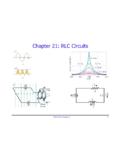
9 Above resonance. unloaded Q varies versus frequency, length, Equation 8 simply represents the ratio of inductive reactance to the series resistance, Rs. Equations 2 and 6 may be combined by taking the absolute value of X in the first numerator term. Equation 9 gives the Q. factor of a series RLC circuit , below and above the resonant frequency. dX. X Z. Q dZ (Eq 9) Figure 1 Q factor of a 2 Rs series RLC circuit . This equation is for computing the Q. factor above and below series resonance. Figure 1 shows an example of the Q factor variation versus frequency as computed from Equation 9 or from Equations 5 and 8. Note that the Q factors calculated by Equations 5. and 8 are equal at the resonant frequency of 44 Sep/Oct 2006. line attenuation and resonator loading such the dielectric losses are much lower than the efficient, , and the phase coefficient, : as capacitive or inductive loads in both open conductor losses for coaxial lines.
10 For those ln 10 and short configurations. lines, we expect the Q factor of opened lines D Ao (Eq 24). (subjected to dielectric losses) to be higher 2000. Estimating the Q factor of a Short than their shorted equivalent (subjected to (Attenuation in neper/foot). Unloaded Resonator conductor losses) only when their length is 2S f In general, Equation 1 above can't be used much below a quarter wavelength. E (Eq 25). to compute the Q factor for a quarter-wave VF ce resonator, since the reactance value X is zero Computing the Q Factor When the Stub (Phase coefficient in radians/foot). or infinite at resonance, and will set the Q to Length is Below or Equal to a Quarter VF is the line velocity factor, ce is the ve- zero or infinity. We also expect a short line Wavelength locity of light in million feet/sec, Ao is the (say 1% of wavelength) to behave as lumped Computing the Q factor of a line requires total attenuation in dB/100 ft and f is the fre- inductance in the case of a shorted line and a knowledge of the attenuation due to quency in MHz.