Transcription of Q - Series Boiler Troubleshooting Manual
1 1 008082013GW Q - Series Boiler Troubleshooting Manual WARNING There are a number of live tests that are required when fault finding this product. Extreme care should be used at all times to avoid contact with energized components inside the product. You MUST be a qualified service person before proceeding with these test instructions. Before checking resistance readings, turn off power source to unit and then isolate each item to be checked from the circuit by unplugging it. When setting gas pressures on one of these units, please check the complete model number you are trouble-shooting.
2 Gas pressures and dip switches can vary among models. Always check the rating plate for complete information and follow directions. If any of the original wire as supplied with the appliance must be replaced, it must be replaced with type 18 AWG wire or its equivalent. Label all wires prior to disconnection when servicing controls. Wiring errors can cause improper and dangerous operation. CAUTION 2 008082013GW Table of Contents Code Numbers Page # Boiler Description .. 4 Error indication (Short reference).
3 5 BL 01 .. 6 BL 05 .. 7 BL 11 .. 8 BL 12 .. 9 BL 60 .. 10 BL 67 .. 11 BL 80 .. 12 BL 81 .. 13 BL 82 .. 14 BL 84 .. 15 BL 85 .. 16 BL 86 .. 17 E 00 .. 18 E 01 .. 19 E 02 .. 20 E 03 .. 21 E 04 .. 22 E 05 .. 23 E 07 .. 24 E 11 .. 25 E 12 .. 26 E 13 .. 27 E 14 .. 28 E 18 .. 29 E 19 .. 30 E 24 .. 31 E 26 .. 32 E 28 .. 33 E 29 .. 34 E 31 .. 35 3 008082013GW E 32 .. 36 E 36 .. 37 E 37 .. 38 E 41 .. 39 E 42 .. 40 E 44 .. 41 E 68 .. 42 E 69 .. 43 E 80 .. 44 E 115 .. 45 Fuse .. 46 Central heating but no domestic hot 47 Hot water but no central heating.
4 47 Central heating installation gets hot without being requested .. 47 Insufficient quantity of hot water .. 48 Temperature drop of the DHW (Combi) .. 48 Radiators do not get hot enough or warming up takes too long .. 48 Checking the 02 .. 49 Boiler Controls .. 50 Explanation of the function buttons .. 51 Starting up filling and de-aerating the Boiler & Water 52 Freeze 53 Filling the heating system .. 54 Altering adjustments .. 55 PARAMETER mode .. 56 Information, Service and Error Modes .. 57 Activating factory setting (Green button function) .. 58 Isolating the Boiler ..59 Reset service interval counter .. 60 2013 Rinnai America Corporation 103 International Drive, Peachtree City, GA 30269 Toll-Free:1-800621-9419 Phone: 678-829-1700 Rinnai is continually updating and improving products; therefore, specifications are subject to change without prior notice.
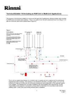
5 Local, state, provincial and federal codes must be adhered to prior to and upon installation. 4 008082013GW 5 008082013GW Parts of the Boiler 6 008082013GW Information displayed in Tech Readout Mode.
6 To enter this mode press and hold the STEP button for 5 seconds. Operation Indication 0 - No heat demand 1 - Fan pre/post purge 2 - Ignition phase 3 - Burner active on central heating 4 - Burner active on DHW 5 - Fan check 6 - Burner off when either DHW or room thermostat is calling * (See note 2 below). 7- Pump overrun phase for central heating 8- Pump overrun phase for hot water 9 - Burner off because of too high flow temperature A - Automatic de-aeration program F Fan test still activated in Service mode H Burner test still activated in Service mode *Note 2; (E Boiler ) a continuous code 6 can mean there is a small hot water leak triggering the plate heat exchanger sensor to call continually for DHW in turn locking out space heating in DHW priority.
7 Switch PARA 36 to 20 (flow switch only) and then repair leak. A detected error is indicated on the display by means of a blocking or error messages. A distinction should be made between these two messages due to the fact that a blocking code can be of a temporary nature, however, error messages are fixed lockouts or hard lockouts. The control will try its utmost to prevent a lockout and will temporary switch off the unit by blocking it, below is a list of some messages the unit will display. Blocks: bL with a number in the last two positions indicates the type of blocking code. bL 01 Block 01: External safety contact cut off. bL 05 Block 05: Outdoor reset sensor not connected. bL 60 Block 60: Incorrect parameter setting of the minimum or maximum power (Btu) of Boiler .
8 BL 67 Block 67: A T has been detected between flow and the return sensor whereas the burner is not in operation. After the T has disappeared the block will clear itself. bL 85 Block 85: The control has not detected water flow. The venting cycle (pro-purge) cycle has started. If during this cycle water flow is detected, the pro-purge cycle stops, the burner will then fire up. Error: E with a number in the last two positions indicates the type of error code. E 00 Error 00: Poor flame forming. E 02 Error 02: No flame forming. E 04 Error 04: Adjustment or error due to voltage interruption. E 05 Error 05: Adjustment.
9 E 12 Error 12: High limit stat. E 18 Error 18: Maximum flow temperature exceeded. E 19 Error 19: Maximum return water temperature exceeded. E 28 Error 28: Fan revolutions not being measured by control board. Flame present when burner is off, electrical interference, poor ground, and flame sensing wire disconnected during off cycle. E 69 Error 69: No or incorrect display. FUSE FUSE: 24 V fuse defective or blown. Block and Errors - Error indication (short reference) NOTE; if the unit appears to be fine but doesn t run and no error code is displayed check; a. That the desired programming is on; set to either Central Heating and/or Domestic Hot Water.
10 B. The unit is not in the Showroom Mode _____ Explanation of T Sensors: T1- Supply sensor - Water leaving heat exchanger mounts in flow of water. T2 - Return water sensor, surface mounted. T3 - Domestic hot water flow sensor,. Q175C uses a surface mount sensor. Q models with optional 3-way valve use a sensor designed to be used in a well. (QP uses a well) T4 Outdoor reset sensor, mounted outside building. T5 - Flue gas sensor - Optional sensor not included with Boiler . 7 008082013GW H If multiple Boiler safeties are to be wired in Series check with your local inspector or the local or State codes to see if this is allowed in your area before proceeding.