Transcription of Q-SYS Acoustic Echo Cancellation - QSC Audio Products
1 Application GuideQ-SYS Acoustic echo CancellationRev. A, February 20162 QSC, LLC / Q-SYS Acoustic echo Cancellation Application GuideAcoustic echo Cancellation (AEC) signal flow and gain structureAEC best practices: Signal flowThis technical note explains how to optimally set up the AEC feature in a Q-SYS design, including setting a useful gain structure. This comprises several basic principles: correct reference signal; seperate AEC channel for each conference mic, mic processing outside the AEC processing loop; end user level controls ahead of the AEC reference an example of best practices in AEC setup, look to the sample conference room designs that Q-SYS Designer and newer install on your these sample designs as examples, or use them as a base or starting point on which to build your own the correct reference signalIn a conferencing system without in-room reinforcement ( voicelift ), everything that goes to the loudspeak-ers should also go to the reference pin.
2 All far-end Audio sources, as well as program material that is heard in the room, go to the reference. A mic signal never should go into its own AEC reference. A mic should never go to the AEC reference of another mic if they are both likely to pick up the same voices or 1. The POTS conference room sample design properly locates mic processing and user level controls (the gain controls in the POTS or VoIP inputs, on the USB endpoint, and the flex stereo input pairs), and also properly mixes signals into the AEC block reference Systems / Q-SYS Acoustic echo Cancellation Application Guide 3 Use a seperate AEC channel for each conferencing mic If there are several mics in the same environment, use a multichannel AEC block with a single reference mic processing after the AEC processing loop The AEC algorithm works best on signals whose processing path is similar to that of the reference end user level controls ahead of the reference pin on the AEC block This applies to any signal being mixed into the reference best practices.
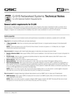
3 Gain structureAfter proper signal flow, we turn our attention to the other big requirement for good conference room deployments: gain structure. This helps ensure a maximal signal-to-noise ratio at each microphone input. We also need to ensure adequate signal levels into the room from the far end or ends and from program 1: Set microphone gainsIn Q-SYS Designer, open the design. Double-click on the analog input block the mics go into. Turn on phantom power, if the mics require it. Have someone speak in a normal voice at a normal level at a normal distance from the nearest mic. Set the channel s input gain knob so that the voice registers between about -15 and -20 dBFS on the meter (see Figure 2). Note that some ceiling mics might require relatively high gain this process for each microphone. However, if all the mics are the same type and are about the same distance from the speaking positions, you might simply set all the mics to the same gain as the ambient noise and signal to noise ratioWatch the meter when no one is speaking and there is no program material playing.
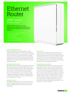
4 This is the noise floor of the room itself. The generally accepted minimum ratio of speech to ambient noise is 15 dB; 25 dB is the desired target. Therefore, the ambient noise in the room should register at most between about -35 and -40 dBFS on the input level meters. If it reads higher, you should consider these possible solutions: Steady-state (constant) noise may be due to HVAC, equipment fans, etc. Using noise reduction in the AEC algorithm may reduce the noise enough to get a good signal-to-noise ratio. To configure noise reduction, open the AEC block and enable noise reduction, then adjust the amount of reduction to eliminate as much noise as 2. Adjust preamp gain so normal speech reaches about -15 to 3. Enabling noise reduction in the AEC QSC, LLC / Q-SYS Acoustic echo Cancellation Application Guide Equalization may help reduce some types of noise but could also negatively affect the sound quality from the microphone.
5 The mic s own self-noise is a physical limitation that can not be mitigated through gain or EQ adjustment; for example, desensitizing the mic (through gain reduction, for example) to reduce the noise floor will also reduce the level of the spoken voice by the same amount. Some types of noise require physical measures, such as Acoustic isolation or 2: Far end gainFor this step, start by turning the power amplifier or amplifiers in the room all the way down. If they have no gain controls for doing this, go into the Q-SYS design and open the output block or blocks that feed them, then pull the Max RMS Output settings on those channels all the way down, to -40 all the user controls to mid position. Then make a test call to or from the the input block for the far-end input ( , POTS In, Softphone In, line input from a codec, or USB Endpoint).
6 With the person at the far end speaking in a normal voice, adjust the input gain of the far end signal so it s approximately equal to the micro-phones, about -15 to -20 the person still speaking normally, increase the amplifier gains (or the output blocks feeding the amps) until the sound level in the conference room is a reasonable level typically, about 65 to 70 dB this point the system should be usable for actual conferencing. Simply adjust the conferencing transmit level so the far-end party can hear the in-room participants loud and and fixesIf the far-end party hears an underwater effect in the Audio picked up by the mics in the conference room, there are probably one or more AEC issues to be corrected. The underwater effect almost always comes from one or more conference room mics being fed into the AEC reference.
7 Make sure no conferencing mics are fed or mixed into the AEC reference pin. If you are working with a teleconferencing codec, make sure AEC is disbled in the codec and that Q-SYS is not feeding the codec s program input. Also make sure that the codec is not in reinforcement mode, which is intended for the codec output to be connected directly to an amplifier input; it loops the conferencing mics back to the AEC reference, which will cause quality issues. The telltale sign is hearing the conferencing mics in the room, when there is local the far-end party hears an echo of his or her own voice: Confirm that the receive signal from the far end, after being routed through the various processing stages, isn t being routed to be transmitted back to the far end. It could also mean that a conferencing mic hears more far end signal than the reference does, which can somewhat confound an AEC algorithm.
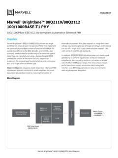
8 To check for this, open the input block for the conferencing mics and watch the meters while the far-end party is talking. Compare them to the level at the AEC Reference pin. If the gain stage in the POTS In or VoIP In signal chain is set to 0 dB, the reference signal Figure 4. Set far end input gain (in the POTS In or VoIP In block) so the level matches that of the conferencing mic Systems / Q-SYS Acoustic echo Cancellation Application Guide 5level should be around -15 to -20 dBFS. If any of the microphone signal levels exceed the reference level, then take one of these corrective measures:Reduce the affected mic preamp gains until their response to the far end signal is about 3 to 6 dB lower than the reference signal. The transmit signal level will need to be increased the reference signal level going into the AEC Reference pin.
9 If necessary, insert a gain object between the user level control and the reference pin and increase the gain so the reference signal, as it responds to the far end signal, is about 3 to 6 dB higher than the conference mics the ratio of reference signal level to conference mic signal level is correct as they both respond to far end speech but the far end still experiences echo , then the cause might be residual echo . If the Tail Length in the Acoustice echo Canceler s Properties block is set to 100 ms, try setting it to 200 ms. (This will take up twice as many DSP resources.) Please note that the default tail length used in the sample designs is already 200 you change the tail length, press F5 or select File > Save to Core & Run. Have the far-end party speak again at a normal level to test the settings. With the far-end party still speaking, set the gain control in the POTS In or VoIP In gain block (after the parametric equalizer block) to maximum.
10 Make sure the power amplifier is not clipping; adjust its gain if necessary. You may also adjust the maximum output of the output block channels to below the amp s clipping you have multiple far end sources (for example, multiple POTS, VoIP, or codec lines), make a test call with each one and calibrate the receive signals to the same 3: Set program gainsProgram sources can vary greatly in level and dynamic range. The key strategy is to set a good nominal level and make sure the peak and transient levels do not clip the Q-SYS analog with the level controls at mid position. Play some suitable material from the program sources and set their input preamp gains so that their average levels register on the input block meters in the range of about -15 to -20 dBFS. With stereo sources, you should set the gains of the left and right channels identically to keep the stereo image centered.