Transcription of Q5/Q5 IR-Probe GAS TRANSMITTER/SENSOR
1 Q5/Q5 IR-Probe GAS TRANSMITTER/SENSOR Q5 IR-Probe INSTALLATION OPERATION AND MAINTENANCE MANUAL QUATROSENSE ENVIRONMENTAL LTD. 5935 OTTAWA STREET, PO BOX 749 (RICHMOND) OTTAWA, ONTARIO CANADA K0A 2Z0 PHONE: (613) 838-4005 FAX: (613) 838-4018 Q5 Operation And Maintenance Manual 85950-001-000 RF August 7, 2015 1 READ BEFORE OPERATING .. 2 1. SPECIFICATIONS .. 2 ELECTRICAL/MECHANICAL SPECIFICATIONS .. 2 sensor SPECIFICATIONS .. 4 2. INSTALLATION .. 6 ENCLOSURES PHYSICAL DIMENSIONS .. 6 TERMINALS .. 6 Wire and Cable.
2 7 Q5 Digital Connection .. 7 RS-485 Terminator .. 7 RS-485 Driver Replacement .. 8 4-20mA and 1-5 VDC / 2-10 VDC Analog Output .. 8 Relays Output .. 9 Note for Q5:.. 9 Certification: .. 9 3. FUNCTION AND CONFIGURATION .. 10 INDICATORS .. 10 RS485-TX/RX .. 10 Relay 1-3 LED .. 10 TOOL FUNCTION .. 11 Enter Main Menu .. 11 Hush Buzzer and Relay .. 11 Reset Latched/Hushed .. 11 Reset MENU Password .. 11 Exit Tool Mode .. 11 MAIN MENU TREE .. 12 MENU 1_SYSTEM SETUP .. 13 System Settings .. 13 MENU 2_ZERO CAL.
3 16 Equipment Required .. 16 Zeroing Calibration Procedure .. 16 MENU 3_SPAN CAL .. 17 MENU 4_OUT TEST .. 18 MENU 5_VIEW SETTING .. 19 MENU 6_ALARM SETUP .. 20 MENU 7_RELAY STYLE .. 21 MENU 8_BUZZER STYLE .. 22 MENU 9_A-OUT SETUP .. 22 MENU A_ALL DISABLE .. 23 MENU B_SIMULATION .. 23 MENU C_SITE SERVICE AND D_FACTROY SET .. 23 4. MODBUS PROTOCOL SUPPORTED BY Q5 .. 23 5. MAINTENANCE .. 24 DVM CONNECTION FOR 4-20MA MEASUREMENT .. 24 4MA AND 20MA OUTPUT CALIBRATION .. 24 SMART sensor ASSEMBLY REPLACEMENT.
4 25 Disassembling .. 25 Replacement 25 Replacement Parts .. 26 Accessories .. 28 6. TROUBLESHOOTING .. 29 Q5 Operation And Maintenance Manual 85950-001-000 RF August 7, 2015 2 READ BEFORE OPERATING All individuals who have or will have the responsibility of using, maintaining, or servicing this product must carefully read this manual. The product will perform as designed only if it is used, maintained, and serviced in accordance with the manufacturer s instructions. The Q5 is a state-of-the-art transmitter that can operate as an independent, stand-alone system or as part of an integrated system.
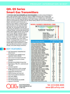
5 The Q5 connects with analog and digital signals to virtually any controller, PLC, or DCS. Setup procedures are simplified with user friendly push buttons and LCD menus. The Q5 IR-Probe is a Q5 with a remote sensing probe that uses the technique of NDIR (Non Dispersive Infrared) to monitor the presence of hydrocarbons and carbon dioxide. The distance between the Q5 and the IR-Probe can up to 100 meters. A 5 meter cable is included in the package. 1. Specifications Electrical/Mechanical Specifications Input Power: 24 VDC nominal, range 18 to 30 VDC, DC Total Max.
6 24 VAC nominal, range 15 to 24 VAC, AC Total Max. (AC must not be grounded) Fuse: F2 on Main Board: Polyswitch 750mA Polyswitch device resets after the fault is cleared and power to the circuit is removed. sensor : Combustible gases: Catalytic or NDIR Toxic gases and Oxygen: Electrochemical Carbon Dioxide: Non-Dispersive Infra-Red (NDIR) Sampling: Diffusion or Pump-through Panel Indicators: 5 Status LED s RS-485 TX Status (Green) RS-485 RX Status (Green) Relay1 Status (Red) Relay2 Status (Red) Relay2 Status (Red) Display: LCD graphic display c/w backlight Keypad: 3 capacitive touch sensing Keys: F1, F2, F3 Q5 Operation And Maintenance Manual 85950-001-000 RF August 7, 2015 3 Relays.
7 3 Relays SPDT, Dry contacts maximum at 30 VDC (resistive load) maximum at 125 VAC (resistive load) Buzzer: 80 db at 10 cm, 2700 Hz Buzzer 1, 2, 3: Programmable tone Tone: chirp once / chirp twice / 50% duty cycle / constant ON Output Signal: RS-485 with QEL Controller Protocol Available Controller: M-Controller & Q4 Controller RS-485 with ModBus protocol 4-20mA and 2-10 VDC Analog Signal Output Enclosure Rating: IP 66 & NEMA 4, 4X, 12 & 13 Operating Temperature: -40 C to 70 C, depends on sensor specification Ambient Humidity: 5% to 95% RH (non-condensing) Storage Temperature: 0 C to 40 C, depends on sensor specification Size: 150mm X 90mm X 65mm Weight.
8 Less than Q5 Operation And Maintenance Manual 85950-001-000 RF August 7, 2015 4 sensor Specifications Code Gas Symbol Gas Density Span Operating Temperature 16 Methane CH4 Lighter 0 - 100%LEL -10 C to +50 C 17 Propane C3H8 Heavier 0 - 100%LEL -10 C to +50 C 18 Hydrogen H2 Lighter 0 - 100%LEL -10 C to +50 C *19 Combustible LEL 0 - 100%LEL -10 C to +50 C *20 Ethylene C2H4 Slightly Lighter 0 - 100%LEL -10 C to +50 C *21 Iso-Butane C4H10 Heavier 0 - 100%LEL -10 C to +50 C *22 Iso-Pentane C5H12 Lighter 0 - 100%LEL -10 C to +50 C *23 Methanol CH3OH Lighter 0 - 100%LEL -10 C to +50 C *24 Benzene
9 C6H6 Lighter 0 - 100%LEL -10 C to +50 C *25 Acetone CH3CO Lighter 0 - 100%LEL -10 C to +50 C *26 Butanol, n-Butane BUTAN Heavier 0 - 100%LEL -10 C to +50 C Code Gas Symbol Gas Density Span Operating Temperature 0 Oxygen O2 0 - 25%VOL -30 C to +55 C Code Gas Symbol Gas Density Span Operating Temperature 1 Carbon Monoxide CO Slightly Lighter 0 250ppm -20 C to +50 C 1 Carbon Monoxide CO Slightly Lighter 0 1000ppm -20 C to +50 C 2 Hydrogen Sulfide H2S Heavier 0 25ppm -20 C to +50 C 2 Hydrogen Sulfide H2S Heavier 0 100ppm -20 C to +50 C 3 Sulphur Dioxide SO2 Heavier 0 6ppm -20 C to +50 C 5 Nitrogen Dioxide NO2
10 Heavier 0 10ppm -20 C to +50 C 6 Hydrogen H2 Lighter 0 1000ppm -20 C to +50 C 6 Hydrogen H2 Lighter 0 2000ppm -20 C to +50 C 7 Hydrogen Cyanide HCN Lighter 0 50ppm -20 C to +50 C 9 Ammonia NH3 Lighter 0 100ppm -30 C to +50 C 9 Ammonia NH3 Lighter 0 1000ppm -30 C to +50 C 11 Ozone O3 Heavier 0 1ppm -20 C to +40 C 13 Chlorine Cl2 Heavier 0 5ppm -20 C to +50 C 14 Chlorine Dioxide ClO2 Heavier 0 2ppm -20 C to +40 C 96 Arsine AsH3 Heavier 0 1ppm -20 C to +40 C 97 Phosphine PH3 Heavier 0 5ppm -20 C to +40 C Q5 Operation And Maintenance Manual 85950-001-000 RF August 7.