Transcription of QCX: 5W CW Transceiver kit assembly instructions
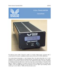
1 QCX assembly Rev 1 QCX CW Transceiver QCX: 5W CW Transceiver kit assembly instructions The QCX : a single band, high performance 5W CW Transceiver with built-in alignment and test equipment, iambic keyer, WSPR beacon mode, and Designed and produced by QRP Labs, 2017 (pictured with Palm Radio pico paddle ) QCX assembly Rev 2 Contents 1. Introduction .. 5 2. Parts list .. 6 3. assembly .. 7 Inventory parts .. 13 Install IC2 socket .. 14 Install DIP integrated circuits IC3, IC5-10 .. 14 Install all 100nF ( , 104 ) capacitors .. 15 Install all 470nF, 474 capacitors .. 16 Install all 1nF, 102 17 Install all 10nF, 103 capacitors .. 17 Install 47nF, 473 capacitors .. 18 Install 39nF, 393 capacitor .. 18 Install , 222 capacitors .. 19 Install 33nF, 333 and , 332 capacitors .. 19 Install capacitors C25 and C26 from the Low Pass Filter kit .. 20 Install capacitors C27 and C28 from the Low Pass Filter kit .. 21 Install capacitor C30.
2 22 Install capacitors C5 and C8 .. 23 Install 1uF, 105 capacitor .. 24 Install 1N4148 diodes .. 24 Install 1N5819 diode .. 25 Install 20 MHz crystal XTAL1 .. 26 Install 27 MHz crystal XTAL2 .. 27 Install all 10K resistors .. 27 Install all 1K resistors .. 28 Install all resistors .. 29 Install all 100-ohm resistors .. 29 Install 120K resistors .. 30 Install 33K resistors .. 30 Install 47K resistors .. 31 Install 36K resistors .. 31 Install 270-ohm resistor R48 .. 32 Install 470-ohm resistor R41 .. 32 Install resistor 33 Install resistor 33 Install resistor 34 Install resistor 34 Install 750K resistor 35 Install 100K trimmer potentiometer R47 .. 35 Install 500-ohm multi-turn trimmer potentiometer .. 36 Install 50K multi-turn trimmer potentiometers .. 36 Install two 100uH inductors .. 37 Install 10uF capacitors .. 38 Install 220uF capacitor C47 (may be supplied as 470uF) .. 39 Install 30pF trimmer capacitor C1.
3 40 QCX assembly Rev 3 Install MPS2907 transistor Q6 .. 40 Install all BS170 transistors .. 41 Install 2x3-pin in-circuit programming header .. 41 Install 4-pin GPS header .. 42 Install 3-pin DVM/RF detector header .. 42 Install 1-pin test points .. 43 Install power connector .. 43 Install 7805 voltage regulator IC11 .. 44 Install pin headers for the LCD 44 Wind and install toroid L4 .. 45 Wind and install toroid L2 .. 47 Wind and install toroids L1 and L3 .. 48 Wind and install transformer T1 .. 49 Install RF output BNC connector .. 55 Install stereo connectors .. 56 Install buttons S2 and S3 (left and right buttons) .. 56 Install rotary encoder .. 57 Install microswitch .. 57 Install gain control potentiometer R36 .. 58 Install four 12mm hex spacers at the LCD corners .. 59 Install four 12mm hex spacers at the PCB corners .. 59 Install knobs .. 60 Install 16-pin female connector on LCD 60 Install microcontroller .. 60 Install LCD and the remaining 4 screws to bolt LCD module.
4 60 Connections for off-board mounting of controls .. 61 Connections for basic operation .. 62 Adjustment and alignment .. 63 4. Operating instructions .. 67 Overview of features .. 67 Display elements .. 69 Operator controls .. 70 Tune rate .. 70 Keyer speed .. 71 RIT .. 71 VFO 72 VFO A/B frequency swap .. 72 Frequency Presets .. 72 Automated message transmission mode .. 73 Menu System .. 73 Saving current operating parameters (VFO frequency etc) .. 74 Types of configuration menu item .. 75 Editing a configuration menu parameter .. 75 Editing a LIST parameter .. 75 Editing a BOOLEAN parameter .. 76 Editing a NUMBER parameter .. 76 Editing a TEXT parameter .. 76 Frequency presets 78 QCX assembly Rev 4 Messages menu .. 78 VFO 79 Keyer menu .. 81 Decoder menu .. 85 Beacon menu .. 87 Other menu .. 94 Alignment menu .. 96 Test equipment .. 100 5. Circuit design of the QCX .. 104 Block diagram and summary .. 104 Circuit diagram.
5 106 Synthesised 106 Transmit/Receive switch .. 107 Band Pass, Phase Splitter, QSD and pre-amps .. 108 90-degree audio phase shift .. 109 CW filter .. 110 Audio amplifier .. 110 Transmit signal routing and PA driver .. 112 Class-E Power Amplifier .. 112 Low Pass Filter .. 114 Key-shaping circuit .. 114 Microcontroller .. 116 Optional GPS interface .. 119 In Circuit Programming (ISP) interface .. 120 Test Equipment .. 120 5V voltage 123 6. Fault-finding .. 123 Blank LCD or blocked LCD .. 123 No backlight at 123 A row of blocks appears on the top row .. 124 DC voltage readings .. 124 RF Power output check .. 126 Audible continuous clicking noise during receive .. 127 7. Measurements .. 128 Equipment .. 128 Transceiver current consumption .. 128 Transmitter power output .. 129 Class-E Power Amplifier drain 130 RF envelope key-shaping .. 130 Low Pass transmitter harmonic output filter characteristics .. 131 Band Pass receiver input filter characteristics.
6 131 Quadrature Sampling Detector bandwidth .. 134 CW Filter response .. 135 Unwanted sideband rejection .. 136 8. Operation reference cheat sheet .. 137 9. Resources .. 138 QCX assembly Rev 5 10. Document Revision History .. 138 1. Introduction Thank you for purchasing this high performance single-band 5W CW Transceiver kit, the QCX (for QRP Labs CW Xcvr). This kit has a long list of features! Easy to build, single-board design, 10 x 8cm, all controls are board-mounted Professional quality double-sided, through-hole plated, silk-screen printed PCB Choice of single band, 80, 60, 40, 30, 20 or 17m Approximately 3-5W CW output (depending on supply voltage) 7-16V recommended supply voltage Class E power amplifier, transistors run even with no heatsinks 7-element Low Pass Filter ensures regulatory compliance CW envelope shaping removes key clicks High performance receiver with at least 50dB of unwanted sideband cancellation 200Hz CW filter with no ringing Si5351A Synthesized VFO with rotary encoder tuning 16 x 2 blue backlight LCD screen Iambic keyer or straight key option included in the firmware Simple Digital Signal Processing assisted CW decoder, displayed real-time on-screen On-screen S-meter Full or semi QSK operation using fast solid-state transmit/receive switching Frequency presets, VFO A/B Split operation, RIT, configurable CW Offset Configurable sidetone frequency and volume Connectors.
7 Power, keyer jack, stereo earphone jack, BNC RF output Onboard microswitch can be used as a simple straight Morse key Built-in test signal generator and alignment tools to complete simple set-up adjustments Built-in test equipment: voltmeter, RF power meter, frequency counter, signal generator Beacon mode, supporting automatic CW or WSPR operation GPS interface for reference frequency calibration and time-keeping (for WSPR beacon) No test equipment is required to build, align and operate this CW Transceiver . Its innovative self-alignment and self-test features will help and guide you in setting up the Transceiver in a few easy steps. The kit also includes a voltmeter, RF power meter, frequency counter and signal generator which can aid in debugging and fault-finding. We hope you enjoy building and operating this kit! Please read this assembly manual carefully, and follow the instructions step by step in the recommended order. Later in the manual the circuit design is described in detail and we recommend reading and understanding this section too, to get the maximum enjoyment and education from your new radio.
8 Typical performance measurements are shown in the measurements section. The operation section of the manual describes Transceiver , alignment and test equipment operation in detail. There is a single page reference cheat sheet near the end of the manual. QCX assembly Rev 6 2. Parts list Resistors (all fixed resistors are -Watt, 1% tolerance) R5, R6, R8, R9 100-ohm (4 pcs), brown-black-black-black-brown R48 270-ohm, red-purple-black-black-brown R41 470-ohm, yellow-purple-black-black-brown R3, 4, 19, 26, 37, 42, 45, 53-55, 62, 63 1K (12 pcs), brown-black-black-brown-brown R12, 13, 15, 16, 20, 22, 23, 25, 44, 56, 59 (11 pcs), orange-orange-black-brown-brown R61 , orange-white-black-brown-brown R18 , yellow-orange-black-brown-brown R11 , green-brown-black-brown-brown R21 , purple-green-black-brown-brown R1, 2, 7, 10, 14, 34, 39, 40, 46, 49-52, 57, 58 10K (15 pcs), brown-black-black-red-brown R28, 29 33K (2 pcs), orange-orange-black-red-brown R30, 31 47K (2 pcs), yellow-purple-black-red-brown R32, 33 36K (2 pcs), orange-blue-black-red-brown R38, 43, 60 120K (3 pcs)
9 , brown-red-black-orange-brown R35 750K, purple-green-black-orange-brown R27 500-ohm multi-turn trimmer potentiometer R17, 24 50K multi-turn trimmer potentiometer (2 pcs) R36 5K Logarithmic potentiometer R47 100K trimmer potentiometer Capacitors C5 22pF, 220 (not used on every band version) C30 30pF, 300 (not used on every band version) C8 39pF, 390 (not used on every band version) C14, 16, 18, 23, 33 1nF, 102 (5 pcs) C19, 20 , 222 (2 pcs) C53 , 332 C4, 7, 10, 42 10nF, 103 (4 pcs) C15 33nF, 333 C17 39nF, 393 C9, 13 47nF, 473 (2pcs) C2, 3, 6, 12, 29, 32, 34-36, 39-41, 48-50, 52 , 104 (16 pcs) C11, 43-46 470nF, 474 (5 pcs) C31 1uF, 105 C21, 2 2, 24, 37, 38, 51 10uF electrolytic (6 pcs) C47 470uF electrolytic C25, C26 Value depends on band, in LPF kit bag (2 pcs) C27, C28 Value depends on band, in LPF kit bag (2 pcs) C1 30pF trimmer QCX assembly Rev 7 Semiconductors D1, 2, 4, 5 1N4148 (4 pcs) D3 1N5819 IC1 SI5351A 10-pin MSOP (pre-soldered at factory) IC2 ATmega328P 28-pin microcontroller IC3 74 ACT00N 14-pin quad NAND gate IC4 FST3253 16-pin SOIC (pre-soldered at factory) IC5-10 LM4562 8-pin dual op-amp (6 pcs) IC11 7805, TO220 5V 1A voltage regulator Q1-5, 7 BS170 TO92 MOSFET (6 pcs) Q6 MPS751 TO92 transistor (MPS2907 in early kits) Inductors L1, 3 Value depends on band, in LPF kit bag (2 pcs) L2 Value depends on band, in LPF kit bag L4 T37-2 (red) toroid, value depends on band L5, 6 100uH axial molded inductors (2 pcs) T1 T50-2 (red) toroid, value depends on band Miscellaneous 2 x 3-pin Male header connector for in-circuit programming 4-pin Male header connector, in LPF kit bag (2 pcs)
10 16-pin Male header connector 16-pin Female header connector 2-pin terminal block 2-pin screw terminal block stereo stereo connector (2pcs) BNC PCB-mounting BNC connector S1 Microswitch S2, 3 6 x 6mm push-to-make button (2 pcs) SW1 Rotary encoder with shaft push-button 16 x 2 LCD HD44780 LCD 1602 with blue backlight XTAL1 20 MHz HC49/4H quartz crystal XTAL2 27 MHz HC49/4H quartz crystal PCB x PCB ( x ) spacer 12mm M3 nylon hex spacers (8 pcs) screw 6mm M3 nylon screws (12 pcs) Knob Knobs to fit rotary encoder and R36 (2 pcs) 3. assembly assembly of this kit is quite straightforward. But there are quite a lot of components. So please keep them methodically in trays or some convenient storage boxes, and be careful not to misplace any. The usual kit-building recommendations apply: work in a well-lit area, with peace and quiet to concentrate. The IC (chips) and some of the other semiconductors in the kit are sensitive to QCX assembly Rev 8 static discharge.