Transcription of Quad, 16-Bit, 2.8 GSPS, TxDAC+® Digital-to-Analog ...
1 Quad, 16-Bit, GSPS, TxDAC+ Digital-to-Analog converter Data Sheet AD9144 Rev. C Document Feedback Information furnished by analog devices is believed to be accurate and reliable. However, no responsibility is assumed by analog devices for its use, nor for any infringements of patents or other rights of third parties that may result from its use. Specifications subject to change without notice. No license is granted by implication or otherwise under any patent or patent rights of analog devices . Trademarks and registered trademarks are the property of their respective owners. One Technology Way, Box 9106, Norwood, MA 02062-9106, Tel: 2014 2019 analog devices , Inc. All rights reserved. Technical Support FEATURES Supports input data rate >1 GSPS Proprietary low spurious and distortion design 6-carrier GSM IMD = 77 dBc at 75 MHz IF SFDR = 82 dBc at dc IF, 9 dBFS Flexible 8-lane JESD204B interface Support quad or dual DAC mode at GSPS Multiple chip synchronization Fixed latency Data generator latency compensation Selectable 1 , 2 , 4 , 8 interpolation filter Low power architecture Input signal power detection Emergency stop for downstream analog circuitry protection Transmit enable function allows extra power saving High performance, low noise phase-locked loop (PLL) clock multiplier digital inverse sinc filter Low power.
2 W at GSPS, W at GSPS, full operating conditions 88-lead LFCSP with exposed pad APPLICATIONS Wireless communications 3G/4G W-CDMA base stations Wideband repeaters Software defined radios Wideband communications Point-to-point Local multipoint distribution service (LMDS) and multichannel multipoint distribution service (MMDS) Transmit diversity, multiple input/multiple output (MIMO) Instrumentation Automated test equipment GENERAL DESCRIPTION The AD9144 is a quad, 16-bit, high dynamic range Digital-to-Analog converter (DAC) that provides a maximum sample rate of GSPS, permitting a multicarrier generation up to the Nyquist frequency. The DAC outputs are optimized to interface seamlessly with the ADRF6720 analog quadrature modulator (AQM) from analog devices , Inc. An optional 3-wire or 4-wire serial port interface (SPI) provides for programming/readback of many internal parameters.
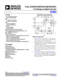
3 Full-scale output current can be programmed over a typical range of mA to mA. The AD9144 is available in an 88-lead LFCSP. TYPICAL APPLICATION CIRCUIT 11675-001 QUADDACAD9144 QUAD MODADRF6720 LPF0 /90 PHASESHIFTERJESD204 BSYSREF SYNCOUTx LO_INMOD_SPIDACDACQUAD MODADRF6720 LPF0 /90 PHASESHIFTERJESD204 BSYNCOUTx LO_INMOD_SPIDACSPICLK DACDAC Figure 1. PRODUCT HIGHLIGHTS 1. Greater than 1 GHz, ultrawide complex signal bandwidth enables emerging wideband and multiband wireless applications. 2. Advanced low spurious and distortion design techniques provide high quality synthesis of wideband signals from baseband to high intermediate frequencies. 3. JESD204B Subclass 1 support simplifies multichip synchronization in software and hardware design. 4. Fewer pins for data interface width with a serializer/ deserializer (SERDES) JESD204B eight-lane interface.
4 5. Programmable transmit enable function allows easy design balance between power consumption and wake-up time. 6. Small package size with 12 mm 12 mm footprint. AD9144 Data Sheet Rev. C | Page 2 of 126 TABLE OF CONTENTS Features .. 1 Applications .. 1 General Description .. 1 Typical Application Circuit .. 1 Product Highlights .. 1 Revision History .. 3 Functional Block Diagram .. 5 Specifications .. 6 DC Specifications .. 6 digital Specifications .. 7 Maximum DAC Update Rate Speed Specifications by Supply .. 8 JESD204B Serial Interface Speed Specifications .. 8 SYSREF to DAC Clock Timing Specifications .. 9 digital Input Data Timing Specifications .. 9 Latency Variation Specifications .. 10 JESD204B Interface Electrical Specifications .. 10 AC Specifications .. 11 Absolute Maximum Ratings .. 12 Thermal Resistance .. 12 ESD Caution.
5 12 Pin Configuration and Function Descriptions .. 13 Terminology .. 16 Typical Performance Characteristics .. 17 Theory of Operation .. 22 Serial Port Operation .. 23 Data Format .. 23 Serial Port Pin Descriptions .. 23 Serial Port Options .. 23 Chip Information .. 25 Device Setup Guide .. 26 Overview .. 26 Step 1: Start Up the DAC .. 26 Step 2: digital Datapath .. 27 Step 3: Transport Layer .. 27 Step 4: Physical Layer .. 28 Step 5: Data Link Layer .. 28 Step 6: Optional Error Monitoring .. 29 Step 7: Optional Features .. 29 DAC PLL Setup .. 30 Interpolation .. 30 JESD204B Setup .. 30 SERDES Clocks Setup .. 32 Equalization Mode Setup .. 32 Link Latency Setup .. 32 Crossbar Setup .. 34 JESD204B Serial Data Interface .. 35 JESD204B Overview .. 35 Physical Layer .. 36 Data Link Layer .. 39 Transport Layer .. 48 JESD204B Test Modes .. 61 JESD204B Error Monitoring.
6 62 Hardware Considerations .. 64 digital Datapath .. 68 Dual Paging .. 68 Data Format .. 68 Interpolation Filters .. 68 digital Modulation .. 69 Inverse Sinc .. 70 digital Gain, Phase Adjust, DC Offset, and Group Delay .. 70 I to Q Swap .. 71 NCO Alignment .. 71 Downstream Protection .. 73 Datapath PRBS .. 75 DC Test Mode .. 75 Interrupt Request Operation .. 76 Interrupt Service Routine .. 76 DAC Input Clock Configurations .. 77 Driving the CLK Inputs .. 77 DAC PLL Fixed Register Writes .. 77 Clock Multiplication .. 77 Starting the PLL .. 79 analog 80 Transmit DAC Operation .. 80 Device Power Dissipation .. 83 Temperature Sensor .. 83 Start-Up Sequence .. 84 Step 1: Start Up the DAC .. 84 Step 2: digital Datapath .. 84 Step 3: Transport Layer .. 85 Data Sheet AD9144 Rev. C | Page 3 of 126 Step 4: Physical Layer .. 85 Step 5: Data Link Layer.
7 86 Step 6: Error Monitoring .. 86 Register Maps and Descriptions .. 87 Device Configuration Register Map .. 87 Device Configuration Register Descriptions .. 95 Outline Dimensions .. 125 Ordering Guide .. 126 REVISION HISTORY 4/2019 Rev. B to Rev. C Changes to Figure 75 .. 76 Updated Outline Dimensions ..125 Changes to Ordering Guide ..126 3/2017 Rev. A to Rev. B Changed Gbps to Gbps, Gbps to Gbps, and Gbps to Gbps .. Throughout Changes to Table 4 .. 7 Change to Device Revision Parameter; Table 14 .. 24 Changes to Function Overview of the SERDES PLL Section .. 36 Changes to Figure 38 .. 37 Changes to Table 97 .. 86 Changes to Table 98 .. 94 6/2015 Rev. 0 to Rev. A Changed Functional Block Diagram Section to Typical Application Circuit Section .. 1 Changes to Figure 1 .. 1 Changed Detailed Functional Block Diagram Section to Functional Block Diagram Section.
8 4 Deleted Reference Voltage Parameter, Table 1 .. 5 Changes to Output Voltage (VOUT) Logic High Parameter, Output Voltage (VOUT) Logic Low Parameter, and SYSREF Frequency Parameter, Table 2 .. 6 Changes to Table 4 .. 7 Changes to Interpolation Parameter, Table 6 .. 8 Deleted Sync Off, Subclass Mode 0 Parameter, Table 7 .. 9 Changed Junction Temperature Parameter to Operating Junction Temperature, Table 10 .. 11 Changes to Terminology Section .. 15 Changes to Figure 26 Caption .. 19 Changes to Figure 29 Caption .. 20 Change to Device Revision Parameter, Table 14 .. 24 Changes to Step 1: Start Up the DAC Section, Table 16, and Table 17 .. 25 Changes to Step 3: Transport Layer Section and Table 19 .. 26 Changes to Table 20 and Table 21 .. 27 Changes to Step 7: Optional Features Section .. 28 Added Table 25; Renumbered Sequentially .. 29 Changes to DAC PLL Setup Section and Table 26.
9 29 Changes to Lane0 Checksum Section .. 30 Changes to Table 30 and Subclass 0 Section .. 31 Changes to Table 33 .. 32 Changes to Table 37 .. 35 Changes to Table 38 .. 36 Added SERDES PLL Fixed Register Writes Section and Table 39 .. 36 Changes to Figure 38 and Table 40 .. 37 Changes to Figure 29 and Data Link Layer Section .. 38 Added Figure 42; Renumbered Sequentially .. 39 Changes to Figure 44 .. 40 Changes to Continuous Sync Mode (SYNCMOD = 0x2) Section .. 42 Changes to Subclass 0 Section .. 43 Changes to Figure 53 .. 50 Changes to Table 49 and Figure 54 .. 51 Changes to Table 50 and Figure 55 .. 52 Changes to Table 51 and Figure 56 .. 53 Changes to Table 52 and Figure 57 .. 54 Changes to Table 53, Table 54, and Figure 58 .. 55 Changes to Table 55 and Figure 59 .. 56 Changes to Table 56 and Figure 60 .. 57 Changes to Table 57 and Figure 61.
10 58 Changes to Table 58 and Figure 62 .. 59 Changes to Power Supply Recommendations Section .. 63 Added Figure 64 .. 64 Changes to Figure 68 .. 66 Changes to Table 66 .. 67 Changes to Table 70, Table 71, Table 72, and I to Q Swap Section .. 70 Changes to Power Detection and Protection Section .. 72 Changes to DC Test Mode Section .. 73 Moved Figure 75 and Table 78 .. 75 Deleted Table 80; Renumbered Sequentially .. 76 Added DAC PLL Fixed Register Writes Section and Table 79 .. 76 Changes to Clock Multiplication Section .. 76 Added Loop Filter Section and Charge Pump Section .. 77 Added Temperature Tracking Section and Table 83 .. 78 Changes to Starting the PLL Section and Figure 79 .. 78 Changes to Transmit DAC Operation Section .. 79 Changes to Self Calibration Section .. 81 Added Figure 86 and Figure 87 .. 81 Changes to Device Power Dissipation Section.