Transcription of Quad Analog-to-Digital Converter (ADC) Data Sheet ADAU1978
1 Quad Analog-to-Digital Converter (ADC) Data Sheet ADAU1978 Rev. A Document Feedback Information furnished by analog Devices is believed to be accurate and reliable. However, no responsibility is assumed by analog Devices for its use, nor for any infringements of patents or other rights of third parties that may result from its use. Specifications subject to change without notice. No license is granted by implication or otherwise under any patent or patent rights of analog Devices. Trademarks and registered trademarks are the property of their respective owners. One Technology Way, Box 9106, Norwood, MA 02062-9106, Tel: 2013 2014 analog Devices, Inc.
2 All rights reserved. Technical Support FEATURES Four 2 V rms differential inputs On-chip phase-locked loop (PLL) for master clock Low electromagnetic interference (EMI) design 109 dB Analog-to-Digital Converter (ADC) dynamic range Total harmonic distortion + noise (THD + N): 95 dB Selectable digital high-pass filter 24-bit stereo ADC with 8 kHz to 192 kHz sample rates digital volume control with autoramp function I2C/SPI controllable for flexibility Software-controllable clickless mute Software power-down Right justified, left justified, I2S, and TDM modes Master and slave operation modes 40-lead LFCSP package Qualified for automotive applications APPLICATIONS Automotive audio systems Active noise cancellation systems GENERAL DESCRIPTION The ADAU1978 incorporates four high performance, analog -to - digital converters (ADCs) with 2 V rms capable ac-coupled inputs.
3 The ADCs use a multibit sigma-delta ( - ) architecture with continuous time front end for low EMI. An I2C/serial peripheral interface (SPI) control port is included that allows a microcontroller to adjust volume and many other parameters. The ADAU1978 uses only a single V supply. The part internally generates the required digital DVDD supply. The low power architecture reduces the power consumption. The ADAU1978 is available in a 40-lead LFCSP package. The on-chip PLL can derive the master clock from an external clock input or frame clock (sample rate clock). When fed with the frame clock, it eliminates the need for a separate high frequency master clock in the system.
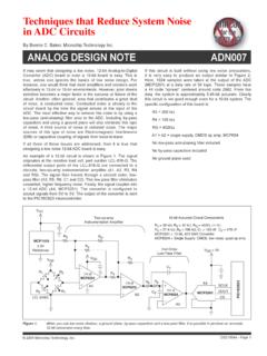
4 Note that throughout this data Sheet , multifunction pins, such as SCL/CCLK, are referred to either by the entire pin name or by a single function of the pin, for example, CCLK, when only that function is relevant. FUNCTIONAL BLOCK DIAGRAM Figure 1. AVDD2 BGREFPROGRAMMABLE GAINDECIMATOR/HPFDC CALIBRATIONSERIAL AUDIO TO Data Sheet Rev. A | Page 2 of 44 TABLE OF CONTENTS Features .. 1 Applications .. 1 General Description .. 1 Functional Block Diagram .. 1 Revision History .. 2 Specifications .. 3 analog Performance Specifications .. 3 digital Input/Output 3 Power Supply 4 digital Filter Specifications .. 4 Timing Specifications.
5 5 Absolute Maximum Ratings .. 7 Thermal Resistance .. 7 ESD Caution .. 7 Pin Configuration and Function Descriptions .. 8 Typical Performance Characteristics .. 10 Theory of Operation .. 12 Overview .. 12 Power Supply and Voltage Reference .. 12 Power-On Reset Sequence .. 12 PLL and Clock .. 13 analog Inputs .. 14 ADC .. 16 ADC Summing Modes .. 16 Serial Audio Data Output Ports, Data Format .. 17 Control Ports .. 21 I2C Mode .. 22 SPI Mode .. 25 Register Summary .. 27 Register Details .. 28 Master Power and Soft Reset Register .. 28 PLL Control Register .. 29 Block Power Control and Serial Port Control Register .. 30 Serial Port Control Register 1.
6 31 Serial Port Control Register 2 .. 32 Channel 1 and Channel 2 Mapping for Output Serial Ports Register .. 33 Channel 3 and Channel 4 Mapping for Output Serial Ports Register .. 35 Serial Output Drive and Overtemperature Protection Control Register .. 36 Post ADC Gain Channel 1 Control Register .. 37 Post ADC Gain Channel 2 Control Register .. 38 Post ADC Gain Channel 3 Control Register .. 38 Post ADC Gain Channel 4 Control Register .. 39 High-Pass Filter and DC Offset Control Register and Master Mute Register .. 40 ADC Clipping Status Register .. 41 digital DC High-Pass Filter and Calibration Register .. 42 Typical Application Circuit.
7 43 Outline Dimensions .. 44 Ordering Guide .. 44 Automotive Products .. 44 REVISION HISTORY 1/14 R e v. 0 t o R e v. A Change to Features Section .. 1 Change to Dynamic Range (A-Weighted) Line Input Parameter, Table 1 .. 3 Change to Figure 9 .. 10 Change to Figure 34 .. 23 Changes to Figure 44 .. 43 5/13 Revision 0: Initial Version Data Sheet ADAU1978 Rev. A | Page 3 of 44 SPECIFICATIONS Performance of all channels is identical, exclusive of the interchannel gain mismatch and interchannel phase deviation specifications. AVDDx/IOVDD = V; DVDD (internally generated) = V; TA = 40 C to +105 C, unless otherwise noted.
8 Master clock = MHz (48 kHz fS, 256 fS mode); input sample rate = 48 kHz; measurement bandwidth = 20 Hz to 20 kHz; word width = 24 bits; load capacitance ( digital output) = 20 pF; load current ( digital output) = 1 mA; digital input voltage high = V; and digital input voltage low = V. analog PERFORMANCE SPECIFICATIONS Table 1. Parameter Test Conditions/Comments Min Typ Max Unit LINE INPUT Full-Scale AC Differential Input Voltage 2 V rms Full-Scale Single-E nded Input Voltage 1 V rms Input Common-Mode Voltage VIN, cm at AINxP/AINxN pins V dc Analog-to-Digital CONVERTERS Differential Input Resistance Between AINxP and AINxN k Single-Ended Input Resistance Between AINxP and AINxN k ADC Resolution 24 Bits Dynamic Range (A-Weighted) Line Input1 Input = 1 kHz, 60 dBFS (0 dBFS = 2 V rms input) 103 109 dB Total Harmonic Distortion + Noise (THD + N) Input = 1 kHz, 1 dBFS (0 dBFS = 2 V rms input)
9 95 88 dB digital Gain Post ADC 0 60 dB Gain Error 10 +10 % Interchannel Gain Mismatch + dB Gain Drift 100 ppm/ C Common-Mode Rejection Ratio (CMRR) 200 mV rms, 1 kHz 50 65 dB 200 mV rms, 20 kHz 56 dB Power Supply Rejection Ratio (PSRR) 100 mV rms, 1 kHz on AVDD = V 70 dB Interchannel Isolation 100 dB Interchannel Phase Deviation 0 Degrees REFERENCE Internal Reference Voltage VREF pin V Output Impedance 20 k ADC SERIAL PORT Output Sample Rate 8 192 kHz 1 This is for a sampling frequency, fS, ranging from kHz to 192 kHz. digital INPUT/OUTPUT SPECIFICATIONS Table 2. Parameter Test Conditions/Comments Min Typ Max Unit INPUT High Level Input Voltage (VIH) IOVDD V Low Level Input Voltage (VIL) IOVDD V Input Leakage Current 10 +10 A Input Capacitance 5 pF OUTPUT High Level Output Voltage (VOH) IOH = 1 mA IOVDD V Low Level Output Voltage (VOL) IOL = 1 mA V ADAU1978 Data Sheet Rev.
10 A | Page 4 of 44 POWER SUPPLY SPECIFICATIONS AVDD = V, DVDD = V, IOVDD = V, and fS = 48 kHz (master mode), unless otherwise noted. Table 3. Parameter Test Conditions/Comments Min Typ Max Unit SUPPLY DVDD On-chip low dropout (LDO) regulator V AVDDx AVDD V IOVDD IOVDD V IOVDD CURRENT Master clock = 256 fS Normal Operation fS = 48 kHz 450 A fS = 96 kHz 880 A fS = 192 kHz mA Power-Down fS = 48 kHz to 192 kHz 20 A AVDDx CURRENT Normal Operation 4-channel ADC, DVDD internal 14 mA 4-channel ADC, DVDD external mA Power-Down 270 A DVDD CURRENT Normal Operation DVDD external mA Power-Down 65 A POWER DISSIPATION Normal Operation Master clock = 256 fS.