Transcription of “Quad II Diaphragm” Models4406 Series Automatic Water ...
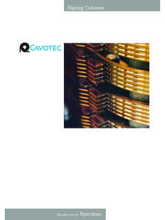
1 (82) (90) (87) Quad II diaphragm Models4406 SeriesAutomatic Water System PumpWith Internal Bypass ValveFEATURES Self-Priming Dry Running Soft, Noise Absorbing Mounts IAPMO listed, 12 Volt Model CSA listed, 12 Volt Model CE Models Available ( )SPECIFICATIONSM otor:Permanent Magnet, Ball Bearing. Pump:Four chamber diaphragm design; Self-primingup to 6 ft. suction lift; Pump able to run drywithout damage; Removable port to :The built-in bypass valve eliminates the needfor an accumulator tank. Do not install in asystem with an accumulator tank. The tankwill interfere with the internal bypass pump switch off, and battery fully charged, fill watertank, open all faucets then turn pump switch on. Waterwill begin to flow, when Water is free of air, turn faucetsoff, remember you are filling the Water heater and thetoilet and shower lines.
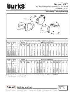
2 When all valves are shut offpump will stop. Should pump fail to stop, turn switch offand see the trouble shooting motor pump unit is equipped with a thermaloverload protection device. In the unlikely event themotor overheats, the pump will shut off. Turn off powerto pump until motor SeriesDimensions - Inches (mm)WeightHeightWidthLengthlb. (kg) (95) (160) (208) ( )AMP DRAWFLOWPRESSURE SWITCHMODEL*VOLTS@ 10 psi ( bar)GPM (l/min)MAX psi (bar)4406-14312V ( )35 ( )4406-343**24V ( )35 ( )4406-043**115V ( )35 ( )* CE fully suppressed models are identified by a prefix R and a CE mark on the label. ( R4406-143).Self Declaration Of Conformance (SDOC) is available upon request.**Not listed with IAPMO or CSAM odel 4406 SeriesSTEP IRemove shipping plugs from Quad pump ports.
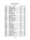
3 Somewater from factory testing may spill 2 Install inlet A and discharge B port connectors. Firmlypush slide clips C forward to lock port connectors 3 Slide rubber mounts fully into 4 mounting 4 Mount pump vertically, with pump head down orhorizontally in an accessible location. If mountingvertically, motor up, attach motor mounts first, thenpump head mounts, while supporting weight of 5 Use 1/2 flexible hose (preferably braided orreinforced). Use hose clamps on the slip-on barb 6 Install no less than 3/8 hose for feed lines tofixtures. Use high pressure hose on all city Water 7 Install a Flojet strainer in an accessible location (forinspection and cleaning) between the tank and pumpinlet.
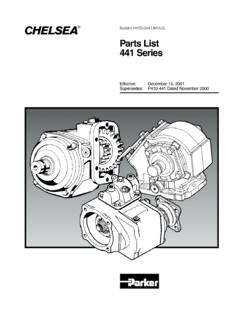
4 This strainer or equivalent is required for pumpwarranty to be : Do not use with an accumulator IUse 14 gauge stranded wire to 20 , 12 gauge to 50 ,from power 2 Use a 10-15 amp rated on-off switch on the (+) positive(red) motor 3 Install 10-15 amp fuse or breaker between the powersource and the positive lead for the -143 models and a4 amp fuse for -343 (+)Fuse(+)SwitchBattery( )Black ( )City WaterInletWaterTankAutofill Tank Valve,Plumb to TankCheckValveFlojet InletStrainerDo Not Plumb Autofillto Pump Suction LineWaterHeaterBACDISASSEMBLEU pper Housing 1. Remove switch (9). Disconnect switch Housing2. Loosen but do not remove four pump head screws andcarefully remove upper housing assembly (1)3.
5 Inspect check valve (2) for debris4. Reassemble new upper housing (1)Check Valve AssemblyFollow step 23. Replace check valve (2)4. Reassemble upper housing (1)Lower Housing, diaphragm , MotorFollow step 2, then slide rubber foot from mounting Rotate lower housing (4) so mounting notch opening on lowerhousing exposes set screw which holds bearing housing Loosen this set screw by inserting wrench 1/8 Allen wrenchinto mounting notch opening. Then, slide lower housing (4) offmotor Cont d 5. 5. Loosen four cam piston screws with Phillips head screwdriver and pull apart cam from inner pistons. (Pistons shouldalways be replaced when a new diaphragm is installed.)Motor Cont d5. Replace MotorREASSEMBLEM otor1.
6 Reassemble lower housing assembly (4) to motor. (Followsteps 4 to 10.)Diaphragm2. Lower housing is assembled with: Flat side of diaphragm and outer pistons facing motor Hex stem of inner pistons must be aligned into hex holes inouter pistons (4). Outer pistons must be aligned with alignment slots on camassembly making sure screw holes align in cam assembly,otherwise diaphragm will Tighten cam piston screws partially, center piston indiaphragm, then tighten screws securely (18 in. lbs. torque)Lower Housing4. Reassemble lower housing assembly (4) to Retighten set screw securely. Set screw head must bepositioned facing motor covering seam (indentation).
7 (Positioning of this screw is critical to avoid misalignment andsubsequent diaphragm damage.)Upper Housing, Check Valve6. Reassemble upper housing (1) and slide clips (8)7. Properly seat O-Ring in check valve assembly (2) and checkif ferrules and screen are in place on upper housing (1)8. Install check valve (2) into upper housing (1) and push Assemble on to lower housing (4), align 4 screws on to motorby rotating lower housing (4) if necessary to align Tighten screws evenly to 30 in. lbs. Switch1. Place switch against front of pump (9), insert screws and takecare not to cross thread or strip out threads in Reconnect : BEFORE SERVICING PUMP, TURN OFF PUMP AND DRAIN Water FROM SYSTEM!!Failure to Prime -Motor operates, but no pump discharge Restricted intake or discharge line Air leak in intake line Debris in pump Punctured pump diaphragm (pump leaking) Crack in pump housingMotor falls to turn on Loose wiring connection Pump circuit has no power Blown fuse or open thermal protector Pressure switch failure Defective motorPulsating Flow - Pump cycles on and off Restricted pump delivery.
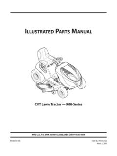
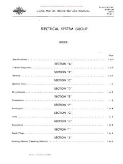
8 Check discharge lines, fittings andvalves for clogging or Fails to Turn Off After All Fixtures Are Closed Empty Water tank Insufficient voltage to pump (low battery) Punctured pump diaphragm (pump leaking) Discharge line leak Defective pressure switchLow Flow and Pressure Air leak at pump intake Accumulation of debris inside pump and plumbing Worn pump bearing (excessive noise) Punctured pump diaphragm (pump leaking) Defective motor2147 Includes items 1 thru 49835 Quite often when a pump is worn or defective the one failed component has overburdened others. To avoid frequent aggravatingrepairs, Flojet offers service kit assemblies making repairs as quick and easy as SeriesStrainer NumberInletOutletScreen4406-XXX1740-0121 /2 BarbQuad Port40 Mesh1740-0021/2 Barb1/2 Barb40 Mesh1740-0041/2 M Qest1/2 M Qest40 Mesh1740-0141/2 M QestQuad Port40 MeshSTRAINERSACCESSORIES20381-000 QUAD PORT x1/2" MALE PORT x1/2" HOSE BARBSTRAIGHT20381-026 QUAD PORT x10/13mm HOSE BARBSTRAIGHT20381-003 QUAD PORT x5/8" HOSE BARBSTRAIGHT20381-008 QUAD PORT x1/2" MALE ELBOW20381-009 QUAD PORT x1/2" HOSE BARB90 ELBOW20381-024 QUAD PORT x10/13mm HOSE BARB90 ELBOWQUICK CONNECT PORT SYSTEMUNITED KINGDOMJ absco/FlojetBingley Road, HoddesdonHertfordshire EN11 OBUTel: +44 (0) 1992 450145 Fax.
9 +44 (0) 1992 467132 CANADAF luid Products Canada55 Royal RoadGuelph, Ontario N1H 1T1 Tel: (519) 821-1900 Fax: (519) 821-2569 JAPANNHK Jabsco Company , Shin-YokohamaKohoku-Ku, Yokohama, 222 Tel: 045-475-8906 Fax: IconFoothill Ranch, CA 92610-3000 Tel: (949) 859-4945 Fax: (949) 859-1153 GERMANYJ absco GmbHOststrasse 2822844 NorderstedtTel: +49-40-53 53 73-0 Fax: +49-40-53 53 73-11 Copyright 2001, ITT IndustriesPrinted in Rights ReservedForm: 81000-23302/02 Automatic Water SYSTEM PUMP SERVICE PARTSWARRANTYFLOJET warrants this product to be free of defects in materialand/or workmanship for a period of two years after purchase bythe customer from FLOJET. During this two year warranty period,FLOJET will at its option, at no charge to the customer, repair orreplace this product if found defective in material or workmanship,with a new or reconditioned product, but not to include costs ofremoval or is only an overview of our limited warranty.
10 If you would like acopy of our warranty, please call or write PROCEDUREP rior to returning any product to FLOJET, call customer service foran authorization number. This number must be written on theoutside of the shipping package. Place a note inside the pack-age with an explanation regarding the reason for return as wellas theauthorization number. Include your name, address andphone #KEY#DESCRIPTION4406-1434406-3434406-043 0 Service Kit*20409-04320409-04320409-0431 Upper Housing With Clips20404-00020404-00020404-0002 Check Valve Assembly20407-03020407-03020407-0303 diaphragm Assembly (includes screws)20403-04020403-04020403-0404 Lower Housing Assembly20419-00120419-00120419-0015 Motor2009-034A2019-009A Motor CE ModelsR2009-034AR2019-008A Motor 115 Volt 2029-044A6 Quad Port x 1/2 HB.