Transcription of Quality Agricultural Equipment
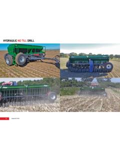
1 Quality Agricultural EquipmentManufacturers of:V-Blades Sweeps Chisels & Spikes Disc Blades drill Discs & Hoe drill Points Related Tillage & Planting Hardware Fertilizer Knives Shanks Coulter Blades Crop SaversPrecision Planting Equipment Conservation Ripper Points Strip Till Points Fertilizer Row UnitsDistributors of:Belted Grain & Fertilizer Conveyors Salt & Material Handling Conveyors Seed Handling Equipment Round Baler Belting Milo Guards & Crop SaversPresidentMike Bergmeier - Ext. 301 Email: PresidentAngie Bergmeier - Ext. 311 Email: SalesOklahoma/Southern Kansas/TexasBrad Gastineau - Ext. 316 Cell: : Kansas/NebraskaAndy Klamm - Ext. 305 Cell: : Sales/ShippingPaul Ehler - Ext.
2 303 Cell: : DepartmentIris Devena - Ext. 308 Email: Hurlbut - Ext. 315 Email: Unit Catalog Table of ContentsOperator s Manual1 3 Standard ADU for 4 X 4 toolbar4 Standard ADU for 7 X 7 toolbar5 ADU Build options sheet6 ADU basic parts breakdown7 Press wheel/tail bracket parts breakdown8 Double spring option parts breakdown9 Double spring conversion kit parts breakdown10 Complete unit and options pricing, Retail prices *11 Parts pricing for all diagrams, Retail prices *12 Press wheel options13 Other popular complete unit schematics14-19 Order planning guide20(800) Box 687 Hutchinson, KS 67504 Fax (620) 662-7482 * Manufacturer s suggested retail price. Your price may vary. ADU OPERATOR S MANUAL Standard Mounts SAFETY FIRST 1.
3 Always secure Equipment with jack stands or blocking when working underneath the Equipment . 2. When setting up 3-point type Equipment with ACRA drill Units, check the rating of the tractors 3-pt. hitch. ADU s weigh approximately 104 lbs ea. or more depending on the options. The additional weight of the ADU s may exceed the tractors capacity causing either loss of steering or hydraulic system damage. In some cases weight may have to be added to the front of the tractor. 3. When installing, removing or adjusting the row width, handle the parallel linkage with extreme caution to avoid injury. Pinch points exist between the parallel linkage and the brackets. CAUTION!!!! When flexing spring equipped linkage, block to prevent accidental spring back and finger injury.
4 4. The ADU disk blades are very sharp and create pinch points. Wear gloves and use extreme caution when rotating blades or adjusting. Keep hands and feet from under the blades. Wear gloves when making all adjustments near the disk blades, seed tube adjustments or spring tension adjustments. Accidental contact with the edge of the disk blade can cause severe lacerations. SET UP AND INSTALLATION 1. To mount ACRA drill Units on a drill , locate the center of each section. Mark the center and work towards both ends measuring and marking the space with each row. Each mark will be the center of a drill unit. NOTE: Minimum row spacing for ADU s with standard brackets is 7 inches. Brackets are available to stagger the rows for more residue clearance.
5 Position the row unit and tighten the U-Bolts. 2. After mounting row units to the bar, install the flexible tube from the feed cup to the drill unit. Secure to the ADU seed tube to insure they stay in place. 3. The ADU Notched disks are set at the factory. To check proper disk clearance. Rotate one disk and it should rotate the other. You should be able to hold one disk and the other should slip against it as you rotate it. The disk should touch and make a scraping sound as they are rotated. 4. Adjusting the gap between the blades is done by adding or removing shims that are behind the blades. Note: the left hand blade is attached with a left hand thread 5/8 bolt and the right hand blade is attached with a right hand thread 5/8 bolt.
6 Shims need to be added or removed to center 1 the V-Slice insert between the blades. You do not need to measure, just visually (eye-ball) it in the center. CAUTION!!!!! Use extreme care when handling the blades. They are extremely sharp and have a pinch point. 5. After approximately 8 hours of operation, check the disk clearance for optimum disk cutting action. OPERATING INSTRUCTIONS ACRA drill Units are designed and built to customer s mounting bar operation height. The standard unit is designed to attach to a mounting bar operating at 18-20 inches above the ground. This will flex the parallel linkage to a working attitude of approximately 45 degrees to the ground. This gives the best performance.
7 There are several bar operation heights being used. Remember, for best performance the parallel link arm should be deflected to approximately 45 degrees. When toolbar height is properly adjusted, parallel linkage will operate between a 30 and a 60 degree angle. To adjust your drill for best possible results, follow this sequence: 1. Level drill toolbar front to back and side to side. This must be done regardless of make or model. Refer to owner s manual for leveling and height adjustments. 2. Adjust spring down pressure for field conditions. Spring tension is set by adjusting the tension bolt. At the factory, it is set at a minimum. Adding two revolutions adjusts to approximately 150 lbs down pressure at the opener V-Slice insert.
8 A total of 8 revolutions will increase it to approximately 230 lbs. Beyond 8 additional revolutions of the tension bolt can cause permanent spring damage by over stretching and permanently deforming the spring. Units with two springs are adjusted the same way, tightening each the same amount. Two springs increase down pressure from 300 lbs to 425 lbs of down pressure. 3. Raise the gage wheel and operate a short distance. Dig down to see where seed is being placed. Remember the seed trench is approximately 3/8 below the bottom of the disk blades. Adjust the gage wheel to maintain the depth that you want to place the seed. NOTE: First time users of these units will initially plant too deep.
9 4. Seed not in the bottom of the trench would indicate the seed tube is too high. Seed tube position is relative to ground speed and soil conditions. The seed tube can be adjusted higher for fast ground speed or wet conditions and lower for slower speeds and dry conditions. 5. ALWAYS WHEN MAKING SHARP TURNS, LIFT THE drill SO THE UNITS ARE OUT OF THE GROUND TO PREVENT DAMAGE TO THE drill UNIT. 6. NEVER BACK UP WITH THE ACRA drill UNIT IN THE GROUND. This will cause the seed tube to plug with soil. NOTE: Periodically check bolts for tightness. TROUBLE SHOOTING 1. Disk plugging Adjust disk gap, soil too wet, disk blades worn 2. Dirt build up Adjust disk gap, soil too wet, disk blades worn 3.
10 Seed tube plugging Lower drill on the move, seed tube too low 4. Planting too deep Back off spring tension, toolbar too low 2 SERVICE AND STORAGE 1. Do not let V-slice insert get too short or rounded-off. Insert must stick below the disk blades at least 1/8 inch. Inserts can be sharpened to a sharp V if rounded off. 2. Disk blade diameter should not be below 14 inches. Residue management is severely reduced when the notch depth is shallow. Always maintain proper blade gap. 3. Each joint of the parallel linkage has a Nylatron bushing for a bearing surface that requires no greasing saving daily maintenance time. These should be checked for wear at the beginning of each season and should be replaced when showing excessive wear.