Transcription of Quick Installation and Operation Guide
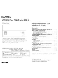
1 LUTRONQ uick Installation and Operation Guide Please ReadThe grafik Eye QS control unit allows for control of both lights and window treatments, without interfaces, using a single control unit. Features include pushbutton scene recall, info screen that displays energy savings and status, IR receiver, astronomic timeclock, contact closure input, and engravable backlit buttons that are easy to find and operate. Model Numbers: QSGRK-3 PCE, QSGRK-4 PCE, QSGRK-6 PCE QSGR-3 PCE, QSGR-4 PCE, QSGR-6 PCEAll units 230 V 50/60 HzQSGRK-3 PCEQSGR-3 PCEQSGRK-4 PCEQSGR-4 PCEQSGRK-6 PCEQSGR-6 PCEUnit Capacity (watts)1 500 W2 000 W2 300 W MLV1 500 VA / 1 200 W2 000 VA / 1 600 W2 300 VA / 1 800 WZone Capacity (watts)40 500 W40 500 W40 500 W MLV40 500 VA / 40 400 W40 500 VA / 40 400 W40 500 VA / 40 400 WSee page 7 for PELV (Class 2: USA) and Functions of the grafik Eye QS ..2 Wiring the grafik Eye QSOverview of Line Voltage/Mains Wiring ..3 Line Voltage Wiring Details.
2 4 Overview of PELV (Class 2: USA) Wiring ..6QS Link Control Wiring Details ..7 Completing Installation of the grafik Eye QS ..8 Programming ModeEntering and Exiting Programming Mode ..9 Navigating Menus in Programming Mode ..9 Wireless Mode ..10 Zone SetupAssign Load Types ..11 Assign Non-Dim Load Type ..11 Setting Load Types ..12 Scene Setup ..13 Activate System Accessories ..14 Faceplate Removal .. 14 Language Selection ..14 Troubleshooting ..15 Warranty, Contact Information ..16 For additional information, see the complete Installation and Operation Guide at olItalianoFran aisDeutschOK1 2 3 4 5 6 Info screenDisplays status or programming functionsScene buttonsWith integral scene indicator LEDsOptional Shade (window treatment) button groupsPreset and raise/lower buttons with integral LEDs (maximum of 3 button groups)Zone numbersZone raise/lower buttonsZone LEDs display current lighting zone levelsTimeclock buttonDisplays current timeclock infoOK buttonUsed for programming, fade timeInfrared receiverFor handheld remote useMaster buttonsTemporarily raise and lower lighting levels on unitUSB type mini BFor programming via PC{Hinged faceplateHinged faceplateFeatures and Functions of the grafik Eye QS grafik Eye QS Quick Installation and Operation Guide 2 For additional information, see the complete Installation and Operation Guide at grafik Eye QS Quick Installation and Operation Guide 3 For additional information, see the complete Installation and Operation Guide at the grafik Eye QS:Overview of Line Voltage/Mains Wiring 4,0 mm2 (12 AWG) each terminal230 VDistribution PanelLine Voltage/Mains Cables and Load Wiring123456 LNIncandescent loadLoad controlled by power moduleTerminal labels:L: Hot/LiveN: Neutral : Ground1-6.}
3 Dimmed/Switched line voltage outputsPower moduleWiring the grafik Eye QS: Line Voltage Wiring Details Use properly certified cable for all line voltage/mains cables. Proper short-circuit and overload protection must be provided at the distribution panel. Install in accordance with all local and national electrical codes. PELV (Class 2: USA) terminals may be temporarily unplugged for ease of IR, occupancy sensor, and control wiring. Notice: Risk of damage to unit . Do not connect line voltage/mains cable to PELV (Class 2: USA) 1: Install wallbox. Mount a 89 mm (3,5-in) deep 4-gang wallbox on a dry, flat indoor surface that is accessible and allows for system programming and Operation . Allow at least 110 mm (4,5 in) clearance above and below the faceplate to ensure proper heat dissipation. Allow 25 mm (1 in) for faceplate overhang on all sides. Note: 4-gang wallbox available from Lutron; P/N 2: Test load wiring. Turn power OFF at the circuit breaker or fuse box.
4 Connect a standard light switch between the live lead and load wire to test the circuit. Turn power ON and check for short or open circuits. If load does not operate, the circuit is open. If the circuit breaker trips (fuse blows or opens), a load short may exist. Correct short or open circuits and test again.`Step 3: Check control unit wiring. Earth/ground terminal connection must be made as shown in wiring diagrams (see page 3). Do not mix different load types on the same zone. Follow all local and national electrical codes when installing PELV (Class 2: USA) wiring with line voltage/mains ! Shock hazard. May result in serious injury or death. Always turn off circuit breaker or remove main fuse from power line before doing any work. Before connecting the loads to the grafik Eye QS control unit, test the loads for overhangs wallbox on all sides; allow 25 mm (1,0 in)110 mm (4,5 in) grafik Eye QS Quick Installation and Operation Guide 4 For additional information, see the complete Installation and Operation Guide at grafik Eye QS Quick Installation and Operation Guide 5 For additional information, see the complete Installation and Operation Guide at the grafik Eye QS: Line Voltage Wiring Details (continued)Step 4: Connect line voltage and loads to control unit.
5 Strip 8 mm (5/16 inch) of insulation off the line voltage/mains cables in the wallbox. Connect the line voltage/mains, ground, and load wires to the appropriate terminals on the back of the control unit. L: Hot/Live N: Neutral : Ground Terminals 1-6: Dimmed/Switched line voltage outputs 8 mm (5/16 inch) The recommended Installation torque is 0,6 N m (5,0 in lbs) for line voltage/mains connections and 0,6 N m (5,0 in lbs) for the earth/ground connection. Note: See page 12 for a list of compatible load types and instructions for programming the grafik Eye QS to properly recognise : Risk of damage to unit. grafik Eye QS control units must be in stalled by a qual i fied electrician in accordance with all applica ble reg u la tions and building codes. Im prop er wiring can result in dam age to control units or oth er equipment. Note: To avoid over heat ing and pos si ble damage to equipment, do not install control units to dim re cep ta cles, mo tor-op erated ap pli ances, or flu o res cent lighting not equipped with Lutron Hi-lume , Eco-10 , or Tu-Wire electronic dim ming ballasts, or other devices approved for your location.
6 In dimmed magnet ic low-voltage cir cuits, you can pre vent trans former overheating and failure by avoid ing excessively high current flow. Do not op erate control units with any lamps re moved or burned out; re place any burned out lamps immediate ly; use only transform ers that in cor po rate ther mal pro tection or fused pri ma ry wind ings. Control units are de signed for res i den tial and commercial use, for indoor use Closure Input WiringFor settings, see the complete Installation and Operation Guide at : Use appropriate wire connecting devices as specified by local : Occupancy sensor(maximum 1)1: COM2: 24 V*3: MUX4: MUXC ontrol WiringWiring the grafik Eye QS:Overview of PELV (Class 2: USA) WiringIR WiringFrom external IR connection (by others)1,0 mm2 (18 AWG) each terminal1,0 mm2 (18 AWG) each terminal1: IR DATA2: IR COMA: CCI SIGB: 24 VC: CCI COMTo control stations, window treatments, or other grafik Eye QS control unitsData (terminals 3 and 4): Twisted, shielded pair 0,5 mm2 (22 AWG) each terminalCommon and power (terminals 1 and 2): Two 1,0 mm2 (18 AWG) each terminal* Do not connect terminal 2 between any grafik Eye QS and any other power supply, including another grafik Eye the complete Installation and Operation Guide at for detailed wiring example.
7 grafik Eye QS Quick Installation and Operation Guide 6 For additional information, see the complete Installation and Operation Guide at System communication uses PELV (Class 2: USA) wiring. Follow all local and national electrical codes when installing PELV (Class 2: USA) wiring with line voltage/mains wiring. Each terminal accepts up to two 1,0 mm2 (18 AWG) wires. Total length of control link must not exceed 610 m (2 000 feet). Make all connections in the control unit s wallbox. Wiring can be T-tapped or daisy-chained. Wire sizes: - Two 1,0 mm2 (18 AWG) conductors for control power. - One twisted, shielded pair of 0,5 mm2 (22 AWG) for data link. - Cable is available from Lutron: GRX-CBL-346S-500 (non-plenum) and GRX-PCBL-346S-500 (plenum). Check compatibility in your area. PELV (Class 2: USA) 24 V 150 smart power panel LUTRONLUTRONLUTRONLUTRONLUTRONLUTRONLUTR ONLUTRONLUTRONLUTRONLUTRONLUTRONT-Tap Wiring Example grafik Eye QS Sivoia QSseeTouch QSWiring the grafik Eye QS:QS Link Control Wiring DetailsSystem Limits The QS wired communication link is limited to 100 devices or 100 zones.
8 Please note the zone count and power draw unit information in the following DeviceZone CountPower Draw Units (supplied)Power Draw Units (consumed)3-zone grafik Eye QS 3 3 04-zone grafik Eye QS 4 3 06-zone grafik Eye QS 6 3 08-zone grafik Eye QS 8 3 016-zone grafik Eye QS 16 3 0seeTouch QS 0 0 1 International seeTouch QS 0 0 1 Sivoia QS 1 0 (Refer to Spec. Submittal)Contact closure interface 5 0 3 Network interface 0 0 2 DMX interface 0 0 2QS smart power panel 0(Refer to Spec. Submittal) 0QS link power supply 0 8 Eye QSSivoia QSseeTouch QSDaisy-Chain Wiring Example QS smart power panel grafik Eye grafik Eye QS Quick Installation and Operation Guide 7 For additional information, see the complete Installation and Operation Guide at Installation of the grafik Eye QS1. Mount the control unit in the wallbox as shown using the four screws pro vid : Follow all local and national electrical codes when installing PELV (Class 2: USA) wiring with line voltage/mains Verify Installation : Restore power.
9 Press the top scene button. The LED will light. Press the zone raise or lower button. Make sure the control unit is dimming all connected loads. 3. Apply the protective overlay to the control unit. See the complete Installation and Operation Guide at for instructions for naming : When tightening mounting screws, make sure that the hinged cover and faceplate will open fully, as shown. Wall200 mm (7,9 in)87 mm (3,5 in)95 mm (3,75 in)Protective overlay (apply after Installation ) grafik Eye QS Quick Installation and Operation Guide 8 For additional information, see the complete Installation and Operation Guide at and Exiting Programming ModeTo enter programming mode:Press and hold the top and bottom scene buttons simultaneously for 3 seconds. The LEDs in the scene buttons will scroll from top to bottom, confirming that you are in programming mode, and the info screen will display the main exit programming mode:Press and hold the top and bottom scene buttons simultaneously for 3 seconds.
10 The info screen will go to Scene Menus in Programming ModeMaster ButtonsThe Master buttons allow you to move through the menu choices. The current choice is highlighted on the info ButtonThe OK button chooses the current highlighted menu choice. This will either take you to the next menu or accept a setting you have selected. When the screen displays a Yes/No question, the OK button is Yes .Timeclock ButtonThe timeclock button functions as a back button during programming mode. Pressing the timeclock button takes you back one step in the current menu. Pressing it repeatedly will eventually return you to the main menu, but will not exit programming mode. When the screen displays a Yes/No question, the Timeclock button is No .Programming ModeOK1 2 3 4 5 6 Press and hold the top and bottom buttons for 3 seconds to enter or exit programming modeMaster buttonsOK buttonTimeclock (back) buttonMain menuScene setupTimeclockScene 1 Fade time 3 seconds grafik Eye QS Quick Installation and Operation Guide 9 For additional information, see the complete Installation and Operation Guide at grafik Eye QS Quick Installation and Operation Guide 10 For additional information, see the complete Installation and Operation Guide at Mode Many models of the grafik Eye QS support wireless communication with other Lutron products.