Transcription of Quick Start Guide - 4rf.com
1 5. Setup the Aprisa SRi radio The Aprisa SRi has a factory default Terminal Operating Mode of Remote Station. One radio in the Aprisa SRi network must be setup as a Base Station. The other radios in the Aprisa SRi network are setup as Remote Stations. Set the Ethernet Operating Mode required. Set the unique radio Network ID to be the same in your entire network including the Base Station ID. Set the Aprisa SRi TX Power and Channel Size to comply with your site license. Setup the Aprisa SRi Zones. Specific channels within the selected zone hop can be disabled if Quick Start Guide there is a known transmission within the channel that may cause interference to the operation of this network. The minimum number of enabled channels is 50. If a channel is selected in a zone that is disabled, the zone will be enabled when the channel selection is saved. The default is all zones enabled. The zone frequencies are pre-defined in the Aprisa SRi for the zone number. The zone frequencies are spaced at the hop frequency of kHz.
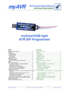
2 You can now configure the remaining terminal and network parameters and settings. Please refer to the Aprisa SRi User Manual for detailed instructions. Aprisa SRi Radio 6. Monitor the Aprisa SRi radio signal strength When the network is installed, the radio signal strength can be Contents monitored on remote stations by setting the radio to Test Mode. To enter Test Mode, press and hold the TEST button on the radio LED. panel until all the LEDs flash green (about 3 - 5 seconds). Follow these steps to operate your Aprisa SRi radio: In Test Mode, the LED Display panel presents a real time visual display of the RSSI. This can be used to adjust the antenna for optimum signal strength. 1. Check the box contents Note: The response time is variable and can be up to 5 seconds. 2. Install the Aprisa SRi radio and connect the protection earth To exit Test Mode, press and hold the TEST button until all the LEDs flash red (about 3 - 5seconds). 3. Connect the Antenna and apply power to the Aprisa SRi radio The OK, MODE and AUX LEDs will be solid green and the TX and RX.
3 LEDs will be solid or flash green if the network is operating correctly. 4. Connect to the Aprisa SRi radio 5. Setup the Aprisa SRi radio 6. Monitor the Aprisa SRi radio signal strength For more information, please refer to the Aprisa SRi User Manual available from the 4RF website (login required). Aprisa SRi Quick Start Guide 2018 4RF Limited. All rights reserved. This document is protected by copyright belonging to 4RF Limited and may not be reproduced or republished in whole or part in any form without the prior written permission of 4RF Limited. While every precaution has been taken in the preparation of this literature, 4RF Limited assumes no liability or errors and omissions, or from any damages resulting from use of this information. The contents and any product specifications within it are subject to revision due to ongoing product improvements and may change without notice. Aprisa and the 4RF logo are trademarks of 4RF Limited. All other marks are the property of their respective owners.
4 1. Check the box contents 3. Connect the antenna and apply power to the Aprisa SRi radio The Aprisa SRi is shipped to you in a box containing the following: Connect the antenna to the antenna port TNC female connector. If the antenna is not available, terminate the TX / Ant'. port with a TNC male 50 ohm terminator (10 Watts min). Aprisa SRi radio fitted with power connector Warning: Do not directly connect the two radio antenna ports without attenuation of at least 40 dB. The receiver can be damaged if signals greater than +10 dBm are applied to the antenna port. The Aprisa SRi is operated from a DC source of voltage between +10 VDC and +30 VDC (negative earth) and consumes up to 35 Watts. External power supplies are available from 4RF as accessories (see the Aprisa SRi User Manual). USB Cable USB A to USB micro B, 1m The power connector (Molex 2 pin female) is supplied fitted to the radio. Wire your power source to the power connector (- / +) and plug the connector into the radio.
5 The connector screws should be fastened to secure the connector. Used for Command Line Interface management see Aprisa SRi User Manual Note: The radio fuses will blow if the connected power supply is over voltage or the polarity is reversed. Two spare fuses are located inside the enclosure (see the Spare Fuses' section of the Aprisa SRi User Manual). Turn your power source on. The radio LEDs will flash orange for one second and then the OK, MODE, AUX LEDs will light solid green and the TX. and RX LEDs will flash red. This is because the factory default Terminal Operating Mode for all Aprisa SRi radios is set to Remote Station. When the radio has been configured and has registered with the network, the TX and RX LEDs will be solid or flash green if the network is operating correctly. 2. Install the Aprisa SRi radio and connect the protection earth The Aprisa SRi radio is ready to operate. The Aprisa SRi has four threaded holes (M4) in the base and two holes (for M5 screws) through the enclosure for mounting.
6 Mounting options Warning: On link operation, RF energy is radiated from the antenna. Do not stand in front of the antenna. include: DIN rail mounting with the Aprisa SRi Mounting Bracket (optional accessory part number APSB-MBRK-DIN'). 4. Connect to the Aprisa SRi radio Wall and rack shelf mounting The Aprisa SRi has a factory default IP address of with a subnet mask of Outdoor enclosures Each radio in the Aprisa SRi network must be setup with a unique IP address on the same subnet. The Aprisa SRi mounting options are shown below: If the IP address of the radio is unknown, it can be changed via the Command Line Interface on the radio MGMT USB port: Connect your PC USB port to the Aprisa SRi MGMT USB port. USB to UART Bridge VCP Drivers are required to connect the radio USB. port to your PC. You can download and install the relevant driver from tools/software/usb-to-uart-bridge-vcp-dr ivers. Login to the radio with the default login admin' and password admin'.
7 At the command prompt >> type cd APRISASR-MIB-4RF' and enter. - type set termEthController1 IpAddress ' and enter. - type set termEthController1 SubnetMask ' and enter. - type set termEthController1 Gateway ' and enter. If the IP address of the radio is known or is the default IP address, it can be changed via the Ethernet port: Setup your PC for a compatible IP address with a subnet mask of Connect your PC network port to one of the Aprisa SRi Ethernet ports. Open a browser and enter Note: The Aprisa SRi has a Self Signed security certificate which may cause the browser to prompt a certificate warning. It is safe to ignore the warning and continue. The valid certificate is Issued By: 4RF-APRISA' which can be viewed in the browser. Login to the radio with the default login admin' and password admin'. Change the IP address, Subnet mask and Gateway to network compatible IP addresses. The Aprisa SRi has an earth connection point on the top left and the top right of the enclosure.
8 Use the supplied M4 screws to earth the enclosure to a protection earth. The antenna feeder cable should use grounding kits for lightning protection as specified or supplied by the coaxial cable manufacturer to properly ground or bond the cable outer. Warning: If the Aprisa SRi is operated in an environment where the ambient temperature exceeds 50 C, the Aprisa SRi must be installed within a restricted access location to prevent human contact with the enclosure heatsink.