Transcription of R-410A ZF SERIES - UPGNET
1 R-410 AZF SERIES 3 - 6 Ton60 Hertz 570568-YIM-A-0310 TABLE OF CONTENTSG eneral .. 2 Installation .. 5 Installation Safety Information.. 5 Limitations .. 5 Location.. 7 Rigging And Handling .. 7 Ductwork .. 12 Condensate Drain .. 12 Compressors.. 12 Filters .. 13 Power And Control Wiring.. 13 Optional Electric Heat .. 38 Options/Accessories .. 41 Economizer And Power Exhaust Set PointAdjustments .. 41 Checking Supply Air CFM .. 50 Operation .. 51 Cooling Sequence Of Operation .. 51No Outdoor Air Options .. 51 Cooling Operation Errors .. 52 Electric Heating Sequence Of Operations .. 53 Electric Heat Operation Errors .. 53 Gas Heating Sequence Of Operations .. 54 Gas Heat Operation Errors .. 54 Flash Codes .. 55 Resets .. 55 Heat Anticipator Setpoints.. 55 Start-up (Cooling) .. 56 Start-up (Gas Heat) .. 56 Checking Gas Input .. 58 Charging The Unit .. 59 Troubleshooting .. 59 Fan On And Off Delays.
2 67 LIST OF TABLES1 ZF036-072 Unit Limitations .. 62 Weights and Dimensions .. 83 ZF036-072 Unit Accessory Weights .. 84 ZF036-072 Unit Clearances .. 105 ZF036-072 Utilities Entry .. 116 Control Wire Sizes .. 147 Electrical Data .. 168 ZF036-072 Physical Data .. 349 Electric Heat Minimum Supply Air .. 3810 Gas Heat Application Data .. 3811 Gas Pipe Sizing - CapacIty of Pipe .. 3912 Altitude/Temperature Correction Factors .. 4313 ZF Blower Performance Side Duct .. 4614 ZF Blower Performance Bottom Duct .. 4815 Belt Drive RPM Selection .. 4916 Indoor Blower Specifications (Belt Drive) .. 5017 Power Exhaust Specifications .. 5018 Additional Static Resistance .. 5119 Electric Heat Limit Setting .. 5320 Electric Heat Anticipator Setpoints .. 5421 single Stage Gas Heat Limit Control Setting .. 5522 2 Stage Gas Heat Limit Control Setting .. 5523 Gas Heat Anticipator Setpoints.
3 5624 Gas Rate-Cubit Feet per Hour .. 5825 Unit Control Board Flash Codes .. 6726 Ignition Control Board Flash Codes .. 67 LIST OF FIGURES1 ZF036-072 Component Location .. 62 Unit 4 Point Load Weight .. 83 Unit 6 Point Load Weight .. 84 Center of Gravity .. 85 ZF036-072 Cooling Only/Electric Heat Front ViewPhysical Dimensions .. 96 ZF036-072 Cooling Only/Gas Heat Front ViewPhysical Dimensions .. 97 ZF036-072 Fixed Outdoor Air Motorized DamperRain Hood Physical Dimensions .. 108 ZF036-072 Disconnect Location .. 109 ZF036-072 Unit Side Duct Openings .. 1110 ZF036-072 Roof Curb .. 1111 Condensate Drain .. 1212 Compressor Restraining Bracket .. 1313 Typical Field Power and Control Wiring .. 1514 Side Entry Gas Piping .. 3915 Bottom Entry Gas Piping .. 3916 Vent And Combustion Air Hood .. 4117 Enthalpy Set Point Chart .. 4218 Honeywell Economizer Control W7212.
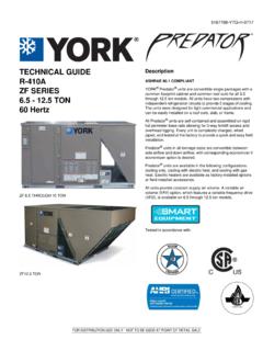
4 4219 Belt Adjustment .. 4220 Altitude/Temperature Correction Factors .. 4321 Pressure Drop Across Coil .. 5022 Gas Valve Piping .. 5423 Typical single Stage Gas Valves .. 5724 Typical 2 Stage Gas Valves .. 5725 Proper Flame Adjustment .. 5726 Typical Flame Appearance .. 5727 ZF036 ( Ton) Operating Pressures .. 6128 ZF048 ( Ton) Operating Pressures .. 6129 ZF060 ( Ton) Operating Pressures .. 6230 ZF072 ( Ton) Operating Pressures .. 6231 Unit Control Board .. 67570568-YIM-A-03102 Johnson Controls Unitary ProductsGeneralYORK Model ZF units are either single package cooling units equipped with optional factory installed electric heaters, or single package gas-fired central heating furnaces with cooling unit. Both are designed for outdoor installation on a rooftop or units are completely assembled on rigid, permanently attached base rails. All piping, refrigerant charge, and electrical wiring is factory installed and tested.
5 The units require electric power, gas connection, duct connections, installation of the weatherproof convenience outlet cover, combustion air inlet hood, flue gas outlet hoods and fixed outdoor air intake damper (units without economizer or motorized damper option only) at the point of supplemental electric heaters have nickel-chrome elements and utilize single point power gas-fired heaters have aluminized-steel (or optional stainless steel) tubular heat exchangers. The units have spark ignition with proven pilot. All gas heaters are shipped from the factory equipped for natural gas use, but can be field converted to Propane with Kit Model #1NP0440 for single stage and Kit Model #1NP0485 for 2 ConsiderationsThis is a safety alert symbol. When you see this symbol on labels or in manuals, be alert to the potential for personal and pay particular attention the signal words DANGER, WARNING or indicates an imminently hazardous situation, which, if not avoided, will result in death or serious indicates a potentially hazardous situation, which, if not avoided, could result in death or serious indicates a potentially hazardous situation, which, if not avoided may result in minor or moderate injury.
6 It is also used to alert against unsafe practices and hazards involving only property installation may create a condition where the operation of the product could cause personal injury or property damage. Improper installation, adjustment, alteration, service or maintenance can cause injury or property damage. Refer to this manual for assistance or for additional information, consult a qualified contractor, installer or service product must be installed in strict compliance with the installation instructions and any applicable local, state and national codes including, but not limited to building, electrical, and mechanical performing service or maintenance operations on unit, turn off main power switch to unit. Electrical shock could cause personal injury. Improper installation, adjustment, alteration, service or maintenance can cause injury or property damage. Refer to this manual. For assistance or additional information consult a qualified installer, service agency or the gas system uses R- 410a Refrigerant which operates at higher pressures than R-22.
7 No other refrigerant may be used in this system. Gage sets, hoses, refrigerant containers and recovery systems must be designed to handle R- 410a . If you are unsure, consult the equipment manufacturer. Failure to use R- 410a compatible servicing equipment may result in property damage or the information in this manual is not followed exactly, a fire or explosion may result causing property damage, personal injury or loss of not store or use gasoline or other flammable vapors and liquids in the vicinity of this or any other TO DO IF YOU SMELL GAS:a. Do not try to light any Do not touch any electrical switch; do not use any phone in your Immediately call your gas supplier from a neighbor s phone. Follow the gas supplier s If you cannot reach your gas supplier, call the fire and service must be performed by a qualified installer, service agency or the gas Controls Unitary Products3 Due to system pressure, moving parts, and electrical components, installation and servicing of air conditioning equipment can be hazardous.
8 Only qualified, trained service personnel should install, repair, or service this equipment. Untrained personnel can perform basic maintenance functions of cleaning coils and filters and replacing all precautions in the literature, labels, and tags accompanying the equipment whenever working on air conditioning equipment. Be sure to follow all other applicable safety precautions and codes including ANSI or latest safety glasses and work gloves. Use quenching cloth and have a fire extinguisher available during brazing soon as a unit is received, it should be inspected for possible damage during transit. If damage is evident, the extent of the damage should be noted on the carrier s freight bill. A separate request for inspection by the carrier s agent should be made in information is available in the following reference forms: Technical Guide - ZF036-072, 251933 General Installation - ZF036-072, 570568 Renewal PartsContact your local York parts distribution center for authorized replacement certified by CSA as use as a cooling only unit, cooling unit with supplemental electric heat or a forced air outdoor installation installation on combustible use with natural gas (convertible to LP with kit).
9 This product must be installed in strict compliance with the enclosed installation instructions and any applicable local, state and national codes including, but not limited to, building, electrical, and mechanical furnace and its individual shut-off valve must be disconnected from the gas supply piping system during any pressure testing at pressures in excess of 1/2 greater than 1/2 PSIG will cause gas valve damage resulting in a hazardous condition. If it is subjected to a pressure greater than 1/2 PSIG, the gas valve must be furnace must be isolated from the gas supply piping system by closing its individual manual shut-off valve during any pressure testing of the gas supply piping system at test pressures equal to or less than 1/2 product must be installed in strict compliance with the enclosed installation instructions and any applicable local, state, and national codes including, but not limited to, building, electrical, and mechanical installation may create a condition where the operation of the product could cause personal injury or property system uses R- 410a Refrigerant which operates at higher pressures than R-22.
10 No other refrigerant may be used in this Controls Unitary ProductsProduct NomenclatureZ F 048N04 A2 AAA10124AZ = A/C, single Pkg., R-410AX = HP, single Pkg., R-410 AProduct CategoryAirflowA = Direct DriveB = Direct Drive/EconomizerD = Direct Drive/Motorized DamperN = Belt DriveP = Belt Drive/EconomizerR = Belt Drive/Motorized DamperT = Belt Drive High StaticU = Belt Drive High Static/EconomizerV = Belt Drive High Static/Motorized DamperProduct Generation2 = Second GenerationC00 = Cooling Only. Suitable for Field Installed Electric HeatHeat Type and Nominal Heat CapacityN04 = 40 MBH Output Aluminized Steel, 1 Stage (036)N06 = 60 MBH Output Aluminized Steel, 1 Stage (048)N08 = 80 MBH Output Aluminized Steel, 1 Stage(036, 060, 072)N10 = 100 MBH Output Aluminized Steel, 1 Stage(048, 060, 072)D06 = 60 MBH Output Aluminized Steel, 2 Stage(036, 048, 060, 072)D10 = 100 MBH Output Aluminized Steel, 2 Stage(036*, 048, 060, 072)S04 = 40 MBH Output Stainless Steel, 1 Stage (036)S06 = 60 MBH Output Stainless Steel, 1 Stage (048)S08 = 80 MBH Output Stainless Steel, 1 Stage(036, 060, 072)S10 = 100 MBH Output Stainless Steel, 1 Stage(048, 060, 072)T06 = 60 MBH Output Stainless Steel, 2 Stage(036, 048, 060, 072)T10 = 100 MBH Output Stainless Steel, 2 Stage(036*, 048, 060, 072)*(D, T)