Transcription of Rack & Pinion Lubrication Systems - ATLANTA …
1 Dimensions in mmZE 11/2015 rack & Pinion Lubrication Systems Page Lubricator 125 cm3 ZE-2 Lubricator 475 cm3 ZE-3 Selection of the Lubrication for rack Drives ZE-4 Lubrication system ZE-5 6 Felt Gear ZE-7 8 Lubrication Equipment, Accessories ZE 9 Lubricating Systems and Accessories ZE 10 Dimensions in mmZE 22/2015 rack & Pinion Lubrication SystemsOrder Code Controlled Lubricators 125 cm3 Fig.
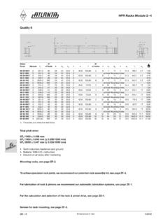
2 3 Fig. 24095 17 6847142 79 Fig. 42403 56 Fig. 6G1/8"Connecting cable, four-core, approx. 5 m longMagnetic sensor65 91 000 1 8 @ @ 91 004 1) 1 8 @ @ 91 006 1 8 @ @ 91 009 1 8 @ @ 91 050 2
3 8 @ @ 91 053 1) 2 8 @ @ 91 054 1) 2 8 @ @ 91 059 2 8 @ @ 91 061 2 8 @ @ 91 001 3
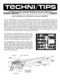
4 Equipment of the lubricator Upgrading option 8 Spare parts @ Assembly tool Kl ber Microlube GB 0Kl ber Structivis AHDW itout greasePipe clampReducer G1/4" to G1/8"SynchronisationDetection of end position2 batteris VExternal power supplyAtexNitrogen pressure chamberAssembly wrench 65 91 030 / cable 65 91 003 / cable, four-coreMagnetic sensorMounting plate 65 91 031 / function is based upon the grease gun principle. After starting the operation, a nitrogen gas is generated electrically which by means of a highly functional construction moves a piston causing the grease filling of 125 cm3 resp.
5 475 cm3 to emerge uni-formly (not pulsatingly) at a constant pressure set to the desired dosage. Depending on the individual requirements, an emptying time of 1-2-3-6-12 or 18 months can be set by means of a micro-switch. It is possible to adjust the grease quantity even after starting the operation by changing the micro-switch position accordingly. Detailed mounting and operating instructions come with every shipment. The transparent housing, which can be mounted in any position, permits the visual inspection of the available grease filling at any time.
6 When completely empty, it can be refilled and used again. Only the nitrogen chamber (Fig. 3 125 cm3, Fig. 9 475 cm3) and the batteries need to be replaced. A permanent signal lamp powered by 2 (125 cm3) resp. 4 (475 cm3) standard V batteries confirms the activation of the lubricator. The contact cable - connected to a potential-free limit switch or contactor (no external power supply required) - permits synchronization with the machine operating time. When using the lubricator 65 91 061 (125 cm3) resp. 65 91 057 (475 cm3) , the connecting cable additionally permits external power supply with 3 V DC.
7 By powering a magnetic sensor (Fig. 2 125 cm3, Fig. 8 475 cm3) with max. 200 mA at 30 V DC the end position (empty condition) indication is transmitted to a yellow LED directly at the sensor or externally to a signal indicator or to your control replenishing the lubricator, consider the following: replace the nitrogen chamber 65 91 001 together with the batteries fill up with lubricant 65 90 002 Microlube GB 0 or 65 90 003 Structovis AHD for closing and opening the lubricator, use the assembly tools 65 91 030 and 65 91 ) When using Structovis AHD, we recommend to position the lubricator lower than the Lubrication point or to use the check valve 65 91 025.
8 Dimensions in mmZE 31/2015 Electrically Controlled Lubricators 475 cm3 Fig. 8 60 120 104180105 Fig. 7135 Fig. 920 Fig. 10 Fig. 11G1/4"143 120 9013530 thickness 130 1052803 thickness67 The function is based upon the grease gun principle. After starting the operation, a nitrogen gas is generated electrically which by means of a highly functional construction moves a piston causing the grease filling of 125 cm3 resp. 475 cm3 to emerge uni-formly (not pulsatingly) at a constant pressure set to the desired dosage.
9 Depending on the individual requirements, an emptying time of 1-2-3-6-12 or 18 months can be set by means of a micro-switch. It is possible to adjust the grease quantity even after starting the operation by changing the micro-switch position accordingly. Detailed mounting and operating instructions come with every shipment. The transparent housing, which can be mounted in any position, permits the visual inspection of the available grease filling at any time. When completely empty, it can be refilled and used again.
10 Only the nitrogen chamber (Fig. 3 125 cm3, Fig. 9 475 cm3) and the batteries need to be replaced. A permanent signal lamp powered by 2 (125 cm3) resp. 4 (475 cm3) standard V batteries confirms the activation of the lubricator. The contact cable - connected to a potential-free limit switch or contactor (no external power supply required) - permits synchronization with the machine operating time. When using the lubricator 65 91 061 (125 cm3) resp. 65 91 057 (475 cm3) , the connecting cable additionally permits external power supply with 3 V DC.