Transcription of Radial Piston Motor (Multi-Stroke) MCR3
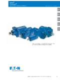
1 Linear Motion andAssembly TechnologiesServicePneumaticsHydraulicsE lectric Drives and ControlsData sheetRadial Piston Motor ( multi - stroke )MCR3RE 15205 1/18 Replaces: 3 XSize 160 to 400 Differential pressure up to 450 barTorque output up to 2300 NmSpeed up to 875 rpmOpen and closed circuitsFeaturesCompact robust construction High volumetric and mechanical efficiencies High pressure rating High reliability Low maintenance Smooth running at very low speeds Low noise Reversible Sealed tapered roller bearings High Radial forces permitted on drive shaft Freewheeling possible Available with optional holding brake ( multi -disc) or dynamic (drum) brakeAvailable with.
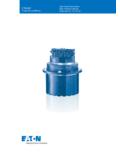
2 Bi-directional two speed -Integrated flushing valve -Speed sensor -ContentsFunctional description 2 Ordering code 4 Schematic diagrams 5 Direction of rotation 5 Technical data 6 Permitted loading on drive shaft 10 Dimensions 11 mcr3 RE 15205 Bosch Rexroth AGFunctional descriptionHydraulic motors type MCR are Radial Piston motors with a rotating part housing (1, 2), rotary group (3, 4), cam (5), drive shaft (6) and flow distributor (7)TransmissionThe cylinder block (4) is connected to the shaft (6) by means of splines. The pistons (3) are arranged radially in the cylinder block (4) and make contact with the cam (5) via rollers (8).
3 Torque GenerationWorking stroke Idle strokeReturnFeedThe number of working and return strokes corresponds to the number of lobes on the cam x number of pistons (8).Flow pathsThe cylinder chambers (E) are connected to ports A and B via the axial bores and the annular passages (D).BearingsTapered roller bearings capable of transmitting high axial and Radial forces are fitted as standard, except on Hydrobase certain applications there may be a requirement to freewheel the Motor . This may be achieved by connecting ports A and B to zero pressure and simultaneously applying a pressure of 2 bar to the housing through port L.
4 In this condition, the pistons are forced into the cylinder block which forces the rollers to lose contact with the cam thus allowing free rotation of the speed operation (2W)In mobile applications where vehicles are required to operate at high speed with low Motor loads, the Motor can be switched to a low-torque and high-speed mode. This is achieved by op-erating an integrated valve which directs hydraulic fluid to only one half of the Motor while continuously re-circulating the fluid in the other half. This reduced displacement mode reduces the flow required for a given speed and gives the potential for cost and efficiency improvements.
5 The Motor maximum speed remains has developed a special spool valve to allow smooth switching to reduced displacement whilst on the move. This is known as soft-shift and is a standard feature of 2W motors. The spool valve requires either an additional sequence valve or electro-proportional control to operate in soft-shift valveIn a closed circuit, the same hydraulic fluid continuously flows between the pump and the Motor . This could therefore lead to overheating of the hydraulic function of the flushing valve option is to replace hydraulic fluid in the closed circuit with that from the reservoir. When the hydraulic Motor is operated under load, either in the clockwise or anti-clockwise direction, the flushing valve opens and takes a fixed flow of fluid through an orifice from the low pressure side of the circuit.
6 This flow is then fed to the Motor housing and back to the reservoir normally via a cooler. In order to charge the low pressure side of the circuit, cool fluid is drawn from the reservoir by the boost pump and is fed to the pump inlet through the check valve. Thus the flushing valve ensures a continuous renewal and cooling of the hydraulic fluid. The flushing feature incorporates a relief valve which is used to maintain a minimum boost pressure and operates at a standard setting of 14 bar (other options available on request). Different orifice sizes may be used to select varying flows of flushing fluid. The following table gives flushing rate values based on a boost / charge pressure of 25 15205 mcr3 Bosch Rexroth AGDynamic brakeWhere mechanical dynamic braking is required, a drum brake may be specified.
7 The drum brake is mounted directly onto the drive shaft (6) and front housing (1). Braking torque is provided by brake shoes acting on the inside of the of brakehydraulic brake fluid (special order required for mineral oil operation)mechanical brake cable (not supplied) 16 Speed sensorA Hall-effect speed sensor (16) may be fitted as an option, giving a two-channel output of phase-displaced square waves, and enabling detection of speed and direction. A toothed target disc (17) is fitted to the Motor cylinder block (4), and the sensor, fitted to a port in the rear case, produces a pulse on each channel as each tooth passes in front of it.
8 The frequency of the pulses is proportional to the rotational are available for use with regulated supplies (Code P1) and for direct connection to a 12 V or 24 V unregulated supply (Code P2).The Motor can also be supplied fitted with a target disc and with a speed sensor port machined, but covered and sealed with a blanking plate (Code P0). These sensor-ready motors may be fitted with a sensor at a later flow rates (for pcharge pcase = 25 bar)Ordering codeFlow ( 1 l/min)F13l/minF25l/minF77l/minF410 brake ( multi -disc brake)MountingBy way of rear housing (2) and brake shaft (16).Brake applicationAs a safety requirement in mobile applications a parking brake may be provided to ensure that the Motor cannot turn when the machine is not in use.
9 The parking brake provides holding torque by means of discs (11) that are compressed by a disc spring (10). The brake is released when oil pressure is ap-plied to brake port Z and the pressure in the annular area (9) compresses the disc spring allowing the brake discs to turn : This brake is provided solely for static use - not to be used release of holding brakeThe brake may also be released manually by loosening screws (13), or by removing plug (14) and inserting a puller into the tapped hole on the brake Piston (15)2912101114151316 Functional DescriptionMCR3 RE 15205 Bosch Rexroth AGOrdering codeRadial Piston motor01 MCRF rame size02 Frame size 33 Housing Type03 Front case flangedAFront case flanged, SAE 4 metric holesDRear case flangedFHigh Radial load bearings fitted, rear case mounting flangeWHydrobase (half Motor )
10 HNominal size, displacement V in cm3/rev160 225 255 280 325 365 40004 Low Displacement: motors use standard cylindrical pistonsLD High Displacement: motors use stepped pistonsHD Drive shaft05 Splined shaft ANSI (only available with housing type A )A45 Parallel keyed shaft 40 mm (only available with housing type D maximum torque 1500 Nm)L40 With flange 180 mm (only available with housing type F and W )F180 Without drive shaft (only available with housing type H )ZThrough shaft06 Without through shaftZSeries07 Series 30 to 39 (series 30 to 39 are dimensionally interchangeable)3 XBrake08 Without brakeA0 hydraulic release spring applied multi -disc holding brake 2200 NmB2 Dynamic brake (drum brake)