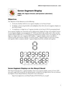
Transcription of RAM Mapping 16*8 LED Controller Driver with keyscan HT16K33
1 RAM Mapping 16*8 LED Controller Driver with keyscanHT16K33 Revision: Date: a 1 011 a 1 011 Rev. a 1 011 Rev. i a 1 011HT16K33 RAM Mapping 16*8 LED Controller Driver with keyscanTable of ContentsFeature ..1 Applications ..1 General Description ..1 Block Diagram ..2 Pin Assignment ..3 Pin Description ..4 Approximate Internal Connections ..5 Absolute Maximum Ratings .. Characteristics .. Characteristics .. Characteristics ..7 Timing Diagrams ..7 Functional Description ..8 Power-on Reset ..8 Standb ode ..8 Wake-up ..9 System Setup Register ..10 ROW/INT Set Register ..10 Display Setup Register ..11 System Oscillator ..12 Display Data Address Pointer ..12 Key Data Address Pointer.
2 12 Register Information Address Pointer ..12 Row Driver Outputs ..12 Column Driver Outputs ..12 Display Memory RAM Structure ..13 LED drive mode waveforms and scanning is as follows: ..13 Digital Dimming Data Input ..15 keyscan ..17Ke scan Timing ..18Ke scan & INT Timing ..18 Key Data Memory RAM Structure ..21 KEY MATRIX CONFIGURATION ..22 When pressing three or more times is assumed: .. When pressing twice or more times is assumed: .. Ke matrix combination with 8 pin package .. 3Ke matrix combination with 4 pin package .. 4 Rev. a 1 011 Rev. 1 a 1 011HT16K33 RAM Mapping 16*8 LED Controller Driver with keyscanKe matrix combination with 0 pin package .. 4I2C Serial Interface.
3 25 Data validit .. 5 START and STOP conditions .. 5B te format .. 5 Acknowledge ..26 Slave Addressing .. Write te write operation .. 8 Page write operation .. 8 Read Operation ..29B te read operation .. 9 Page read operation .. 9 Command Summary ..30HT16K33 operation flow chart ..3 Application Circuit ..34 LED Matrix Circuit ..37 Package Information ..38 0-pin SOP (300mil) Outline Dimensions ..38 4-pin SOP (300mil) Outline Dimensions ..39 8-pin SOP (300mil) Outline Dimensions ..40 Reel Dimensions ..41 Carrier Tape Dimensions ..4 Rev. a 1 011 Rev. 1 a 1 011HT16K33 RAM Mapping 16*8 LED Controller Driver with keyscanFeature Operating voltage: ~ Integrated RC oscillator I2C-bus interface 16*8 bits RAM for display data storage Max.
4 16 x 8 patterns, 16 segments and 8 commons R/W address auto increment Max. 13 x 3 matrix key scanning 16-step dimming circuit Selection of 20/24/28-pin SOP package typesApplications Industrial control indicators Digital clocks, thermometers, counters, multimeters Combo sets VCR sets Instrumentation readouts Other consumer applications LED DisplaysGeneral DescriptionThe HT16K33 is a memory Mapping and multi-function LED Controller Driver . The max. Display segment numbers in the device is 128 patterns (16 segments and 8 commons) with a 13*3 (MAX.) matrix key scan circuit. The software configuration features of the HT16K33 makes it suitable for multiple LED applications including LED modules and display subsystems.
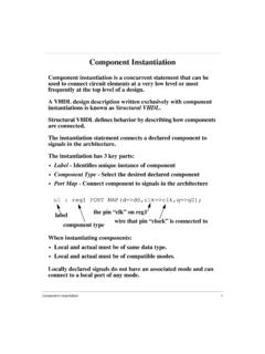
5 The HT16K33 is compatible with most microcontrollers and communicates via a two-line bidirectional a 1 011 Rev. 3 a 1 011HT16K33 RAM Mapping 16*8 LED Controller Driver with keyscanBlock DiagramRowdriveroutputInterruptfunctiono utputKe datainputDeviceaddressdatainputDispla RA 1 *8bitsTiminggeneratorI CControllerCO 0/ADCO 1/KS0CO /KS1CO 3/KS ROW0/A VDDVSSSDASCLP ower_onresetCO 5CO CO 7CO 4 PORPORROW1/A1 ROW1 /K10 ROW15/K13/INTKe dataRA 13*3bitsPORROW13/K11 ROW14/K1 ROW /A0 ROW3/K1 InternalRCOscillatorCommonscanoutputKe scanoutputDeviceaddresssourceoutputA[ :0]PORPORPORPORRev. a 1 011 Rev. 3 a 1 011HT16K33 RAM Mapping 16*8 LED Controller Driver with keyscanPin Assignment242322212019181716151413123456 789101112 VSSCOM0/ADCOM1/KS0 COM2/KS1 COM3/KS2 COM4 COM5 COM6 COM7 ROW11/K10/INTROW10/K9 ROW9/K8 VDDSDASCLROW0/A1 ROW1/A0 ROW2/K1 ROW3/K2 ROW4/K3 ROW5/K4 ROW6/K5 ROW7/K6 ROW8/K7HT16K3324 SSOP-A2019181716151413121112345678910 VSSCOM0/ADCOM1/KS0 COM2/KS1 COM3/KS2 COM4 COM5 COM6 COM7 ROW7/K8/INTVDDSDASCLROW0/K1 ROW1/K2 ROW2/K3 ROW3/K4 ROW4/K5 ROW5/K6 ROW6/K7HT16K3320 SSOP-A2827262524232221201918171615123456 7891011121314 VSSCOM0/ADCOM1/KS0 COM2/KS1 COM3/KS2 COM4 COM5 COM6 COM7 ROW15/K13/INTROW14/K12 ROW13/K11 ROW12/K10 ROW11/K9 VDDSDASCLROW0/A2 ROW1/A1 ROW2/A0 ROW3/K1 ROW4/K2
6 ROW5/K3 ROW6/K4 ROW7/K5 ROW8/K6 ROW9/K7 ROW10/K8HT16K3328 SSOP-AHT16K3320 SOP-A24232221201918171615141312345678910 1112 VSSCOM0/ADCOM1/KS0 COM2/KS1 COM3/KS2 COM4 COM5 COM6 COM7 ROW11/K10/INTROW10/K9 ROW9/K8 VDDSDASCLROW0/A1 ROW1/A0 ROW2/K1 ROW3/K2 ROW4/K3 ROW5/K4 ROW6/K5 ROW7/K6 ROW8/K7HT16K3324 SSOP-A2019181716151413121112345678910 VSSCOM0/ADCOM1/KS0 COM2/KS1 COM3/KS2 COM4 COM5 COM6 COM7 ROW7/K8/INTVDDSDASCLROW0/K1 ROW1/K2 ROW2/K3 ROW3/K4 ROW4/K5 ROW5/K6 ROW6/K7HT16K3320 SSOP-A2827262524232221201918171615123456 7891011121314 VSSCOM0/ADCOM1/KS0 COM2/KS1 COM3/KS2 COM4 COM5 COM6 COM7 ROW15/K13/INTROW14/K12 ROW13/K11 ROW12/K10 ROW11/K9 VDDSDASCLROW0/A2 ROW1/A1 ROW2/A0 ROW3/K1 ROW4/K2 ROW5/K3 ROW6/K4 ROW7/K5 ROW8/K6 ROW9/K7 ROW10/K8HT16K3328 SSOP-AHT16K3324 SOP-A24232221201918171615141312345678910 1112 VSSCOM0/ADCOM1/KS0 COM2/KS1 COM3/KS2 COM4 COM5 COM6 COM7 ROW11/K10/INTROW10/K9 ROW9/K8 VDDSDASCLROW0/A1 ROW1/A0 ROW2/K1 ROW3/K2 ROW4/K3 ROW5/K4 ROW6/K5 ROW7/K6 ROW8/K7HT16K3324 SSOP-A2019181716151413121112345678910 VSSCOM0/ADCOM1/KS0 COM2/KS1 COM3/KS2 COM4 COM5 COM6 COM7 ROW7/K8/INTVDDSDASCLROW0/K1 ROW1/K2 ROW2/K3 ROW3/K4 ROW4/K5 ROW5/K6 ROW6/K7HT16K3320 SSOP-A2827262524232221201918171615123456 7891011121314 VSSCOM0/ADCOM1/KS0 COM2/KS1 COM3/KS2 COM4 COM5 COM6 COM7 ROW15/K13/INTROW14/K12 ROW13/K11 ROW12/K10 ROW11/K9 VDDSDASCLROW0/A2 ROW1/A1 ROW2/A0 ROW3/K1 ROW4/K2 ROW5/K3 ROW6/K4
7 ROW7/K5 ROW8/K6 ROW9/K7 ROW10/K8HT16K3328 SSOP-AHT16K3328 SOP-ARev. a 1 011 Rev. 5 a 1 011HT16K33 RAM Mapping 16*8 LED Controller Driver with keyscanPin DescriptionPin NameTypeDescriptionSDAI/OI C interface Serial Data Input/OutputSCLII C interface Serial Clock InputVDD Positive power suppl for logic circuitVSS Negative power suppl for logic circuit groundCO 0/ADO Common output pin active low during displa Also used as device address source output pin active high during power on reset and ke scanCO 1/KS0~CO 3/KS O Common output pin active low when displa ing Also used as the Ke source output pin active high during ke scan operationCO 4~CO 7O Common outputs pin active low during displa.
8 28 Pin packageROW0/A ~ROW /A0I/O ROW output pin active high when displa ing Also used as the device address data input pin internal pull-low during power on reset and during ke scan operationROW3/K1~ROW14/K1 I/O ROW outputs pin active high during displa . Also used as the Ke data input pin internal pull-low during ke scan operationROW15/K13 /INTI/O When the INT/ROW bit of ROW/INT set register is set to 0 this pin become a Row Driver output pin active high when displa ing and Ke data input during ke scan operation. When the INT/ROW bit of ROW/INT set register is set to 1 this pin become Interrupt signal (INT) output pin. INT pin output active-high when the act bit of the Row/int setup register is set to 0.
9 INT pin output active-high when the act bit of the ROW/INT register is set to 1 .24 Pin packageROW0/A1~ROW1/A0I/O ROW output pin active high when displa ing Also used as the device address data input pin internal pull-low during a power on reset and during a ke scan operationROW /K1~ROW10/K9I/O ROW outputs pin active high when displa ing Also used as the Ke data inputs pin internal pull-low during a ke scan operationROW11/K10/INTI/O When the INT/ROW bit of ROW/INT set register is set to 0 this pin become a Row Driver output active high when displa ing and Ke data input during a ke scan operation When the INT/ROW bit of ROW/INT set register is set to 1 this pin become an Interrupt
10 Signal (INT) output pin. INT pin output active-high when the act bit of the Row/int setup register is set to 0 . INT pin output active-high when the act bit of the Row/int setup register is set to 1 .20 Pin packageROW0/K1~ROW /K7I/O ROW output pin active high when displa ing Also used as the Ke data inputs pin internal pull-low during a ke scan operationROW7/K8 /INTI/O When the INT/ROW bit of the ROW/INT setup register is set to 0 this pin become a Row Driver output active high when displa ing and Ke data input during a ke scan operation When the INT/ROW bit of the ROW/INT set register is set to 1 this pin become an Interrupt (INT)