Transcription of RC Circuits - Michigan State University
1 Experiment4RC Objectives Observe and qualitatively describe the charging and discharging (de-cay) of the voltage on a capacitor. Graphically determine the time constant for the IntroductionWe continue our journey into electric Circuits by learning about anothercircuit component, the capacitor. Like the name implies, capacitors havethe physical capability of storing electrical charge. Many things can beaccidental capacitors. Most electrical components have some amount ofcapacitance within them, but some devices are specifically manufacturedto do the sole job of being capacitors by capacitors intoday s lab will lose their charge rather quickly, but still slowly enough forhumans to watch it happen. Capacitors in electrical Circuits can have verydi erent characteristic times for charging and , in fact, are actually capacitors that discharge very, very slowly (they takea while to lose their charge) and can lose their overall e ectiveness through that RC Key ConceptsAs always, you can find a summary online at : electricity and magnetism (capacitor, charging of a capacitor)To play with building Circuits with capacitors, or to get a head starton trying out the Circuits for today, run the computer simulation TheoryThe parallel-plate capacitor: two flat metal plates placed nearly parallel andseparated by an insulating material such as dry air, plastic or ceramic.
2 Sucha device is shown schematically in is a description of how a capacitor stores electrical energy. Ifwe connect the two plates to a battery in a circuit, as shown in ,the battery will drive charges around the circuit as an electric the charges reach the plates they can t go any further because of theinsulating gap so they collect on the plates, one plate becoming positivelycharged and the other negatively charged. This slow buildup of electriccharge actually begins to resist the addition of more charge as a voltage2 : Schematic of a capacitor in a circuit with a updated February 5, Theorybegins to build across the plates, thus opposing the action of the a consequence, the current flowing in the circuit gets less and less ( itdecays), falling to zero when the back-voltage on the capacitor is exactlyequal and opposite to the battery we were to quickly disconnect the battery without touching the plates,the charge would remain on the plates.
3 You could literally walk around withthis stored charge. Because the two plates have di erent signs of electriccharge, there is a net electric field between the two plates. Hence, thereis a voltage di erence across the plates. If, some time later, we connectthe plates again in a circuit, say this time with a light bulb in place ofthe battery, the plates will discharge through the bulb: the electrons onthe negatively charged plate will move around the circuit through the bulbto the positive plate until all the charges are equalized. During this shortdischarge period a current flows and the bulb will light up. The capacitorstored electrical energy from its original charging by the battery and thendischarged it through the light bulb.
4 The speed with which the dischargeprocess (and conversely the charging process) can take place is limited bythe resistanceRof the circuit connecting the plates and by the capacitanceCof the capacitor (a measure of its ability to hold charge).RC CircuitAn RC circuit is a circuit with a resistor and a capacitor in series connectedto a voltage source such as a with Circuits made up only of resistors, electrical current can flow inthis RC circuit with one modification. A battery connected in series ,whichdecaysgraduallytozero as the capacitor charges up. If the battery is removed and the circuitreconnected without the battery, a current will flow (for a short time) intheoppositedirection as the capacitor discharges. A measure of howlong these transient currents last in a given circuit is given by thetimeconstant.
5 The time it takes for these transient currents to decay depends on theresistance (R)andcapacitance(C). The resistor resists the flow of current;it thus slows down the decay. The capacitance measures capacity tohold charge: like a bucket of water, a larger capacity container takes longerto empty than a smaller capacity container. Thus, the time constant ofLast updated February 5, 2014614. RC Circuitsthe circuit gets larger for ,usingtheunitsofcapacitance which are farads , (seconds) =R(ohms) C(farads)( )Isn t it strange that ohms times farads equals seconds? Like many thingsin the physical world, it is just not intuitive. We can at least show thisby breaking the units down. From Ohm s Law,R= amount of charge flowing per time, soI= to how much charge can be stored per voltage applied, orC= ,RC=R C=VI QV=QI=QQ/t=tThe current does not fall to zero at time.
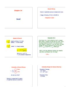
6 Instead, is the time it takesfor the voltage of the discharging capacitor to drop to 37% of its originalvalue. It takes 5 to 6 as it takes time for the charged capacitor to discharge, it takes time tocharge the capacitor. Due to the unavoidable presence of resistance in thecircuit, the charge on the capacitor and its stored energy only approachesan essentially final (steady- State ) value after a period of several times thetime constant of the circuit elements updated February 5, Theory(a) Charging(b) DischargingFigure : Schematics of charging and discharging a and discharging the RC circuitChargingInitially, a capacitor is in series with a resistor and disconnected from abattery so it is uncharged. If a switch is added to the circuit but is open,no current flows.
7 Then, the switch is closed as in (a). Now thecapacitor will charge up and its voltage will increase. During this time, acurrent will flow producing a voltage across the resistor according to Ohm sLaw,V=IR. As the capacitor is charging up the current is actuallydecreasing due to the stored charge on the capacitor producing a voltagethat increasingly opposes the current. Since the current through the resistor(remember the resistor and capacitor are in series so the same current flowsthrough both) is decreasing then by Ohm s law so is the resistor s the behavior of the voltage across the capacitor and resistoras a function of the time constant, , of the circuit for a charging that as the capacitor is charging, the voltage across the capacitorincreases but the voltage across the resistor the capacitor is charging, the voltages across the capacitor,VC,and resistor,VR,canbeexpressedasVC(t)=V0 1 e t ( )VR(t)=V0e t ( )
8 Whereeis the base of the natural logarithm andV0is the initial value ofeis approximately Remember that the time constant of a circuit depends on capacitance and resistance as =RC. When thetimetis exactly equal to 1 time constant thent= and the previousequations becomeLast updated February 5, 2014634. RC CircuitsVC=V0 1 e 1 ( )VR=V0 e 1 ( )This means that aftert= seconds, the capacitor has been chargedto 63% of its final value and the voltage across the resistor has dropped to37% of its peak (initial) value. After a very long time, the voltage acrossthe capacitor will essentially be equal to the battery s voltage,V0,andthevoltage across the resistor will be (for all practical purposes) zero.(a) Voltage across the capacitorVC.
9 (b) Voltage across the : Voltage in RC circuit components as a function of time for acharging capacitor where the time constant = we flip the switch to the position shown in (b),sothatthebatteryis no longer included in the circuit, we will discharge the capacitor. Nowthe charge stored on the capacitor is free to leave the plates and will causea current to flow. The current will be the largest at the beginning,t=0,and will decay away as charge leaves the capacitor s plates. Since the cur-rent is decreasing the voltage di erence across the resistor is also decreasing(Ohm s law again). the behavior of the voltage across thecapacitor and resistor as a function of the time constant, ,ofthecircuitfor a discharging capacitor.
10 For the case when the capacitor is dischargingnotice that both the voltage across the capacitor and the resistor are de-caying to zero. It is critical to remember that the total voltage between thecapacitor and the resistor must add up to the applied voltage (Kirchho sloop law). When the circuit is disconnected from the power supply, then64 Last updated February 5, Theory(a) Voltage across the capacitorVC.(b) Voltage across the : Voltage in RC circuit components as a function of time for adischarging capacitor where the time constant = sum of the voltages must be zero so the graph of the voltage across theresistor must be increasing from V0to the case when the capacitor is discharging, the voltages across thecapacitor,VC,andresistor,VR,aregivenb yVC=V0e t ( )VR= V0e t ( )Compare these equations to the ones given for when the capacitor ischarging and make sure you understand the di is usually easier to interpret a graph when the plot gives a straightline.