Transcription of RCI-2985DX TABLE OF RCI-2995DX CONTENTS - textfiles.com
1 - 1 -RCI- 2985dx RCI- 2995dx TABLE OF CONTENTS PAGECHAPTER 1 SPECIFICATIONS General ..2 Transmitter ..2 Receiver ..2 CHAPTER 2 INTRODUCTION Introduction ..3 Features ..3 CHAPTER 3 OPERATION Introduction ..4 Control & Connections ..4 Microphone ..9 Operation ..9 CHAPTER 4 PROGRAMMING Introduction ..12 Frequency Selection ..12 Frequency Scanning ..12 Offset Frequency Operation ..14 CHAPTER 5 CIRCUIT DESCRIPTION Introduction ..15 PLL Circuit ..15 Receiver Circuit ..15 Transmitter Modulation Circuit ..15 Transmitter Amplifier Circuit ..15 CHAPTER 6 ALIGNMENT Required Test Equipment ..20 Alignment Procedures ..20 CHAPTER 7 MAINTENANCE Precautions ..24 Periodic Inspection ..24 Fuse Replacement ..24 CHAPTER 8 DIAGRAMS AND PART LIST PCB Layout & Part List.
2 25 - 2 -RCI- 2985dx RCI- 2995dx CHAPTER 1 SPECIFICATIONS GENERAL Model RCI- 2985dx / RCI- 2995dx Frequency Range 12 meter : ~ MHz 10 meter : ~ MHz Tuning Steps 100 Hz, 1 KHz, 10 KHz, 100 KHz, 1 MHz Emission Modes AM(A3) / FM(F3) / LSB, USB(A3J) / CW(A1) Frequency Control Dual Phase-Lock-Loop (PLL) synthesizer Frequency Tolerance Frequency Stability Operating Temperature Range -10 C to +50 C Microphone Plug-in (6 pin), Dynamic PTT Meter Function Meter #1 : Indicates relative RF Power Output / Antenna SWR Meter #2 : Indicates Received Signal Strength / AM Modulation Level Input Voltage 110V 60Hz ( 220V 50Hz Optional) Antenna Connector UHF, SO-239 TRANSMITTER RF Power Output : RCI- 2985dx : RCI- 2995dx CW/AM/FM : 10W RMS ; USB/LSB : 25W PEP CW/AM/FM : 50W RMS ; USB/LSB : 150W PEP SSB Generation Dual-Balanced Modulation AM Modulation High and Low level Class B, Amplitude Modulation FM Deviation 4 KHz @ 1 KHz 30mV Audio ( 5 KHz max.)
3 Clarifier Range 5 KHz Harmonic and Spurious Emissions > 60dB AM/FM Frequency Response 400 to 5000 Hz SSB Frequency Response 400 to 3000 Hz Output Impedance 50 Ohms Output Indicators RF Meter shows relative RF Output Power RECEIVER Sensitivity AM/CW : < V For 10dB S+N/N FM : < V For 12dB S+N/N USB/LSB : < V For 10dB S+N/N AM/FM Selectivity 50dB at 10 KHz SSB Selectivity 60dB at 4 KHz Image Rejection Ratio > 50dB IF Rejection > 80dB Automatic Gain Control (AGC) Figure Of Merit SSB/CW/AM : 80dB for 50mV for 10dB Change in Audio Output Squelch Adjustable-Threshold less than V Audio Frequency Response 400 to 2500 Hz Distortion < 10% at 2 Watts Output Adjacent Channel Rejection >50dB Cross Modulation >50dB Intermediate Frequency MHz (AM-1st, SSB), 445 KHz (AM-2nd) Clarifier Range 5 KHz Noise Blanker IF Signal Gate Type Audio Output Power 3W @ 10% THD Built-in Speaker 8 Ohms, 4 Watts External Speaker (Optional) 8 Ohms, 4 Watts (SPECIFICATIONS SUBJECT TO CHANGE WITHOUT NOTICE) - 3 -RCI- 2985dx RCI- 2995dx CHAPTER 2 INTRODUCTION INTRODUCTION The Ranger RCI- 2985dx / RCI- 2995dx is a solid-state, fully synthesized Amateur 10 and 12 meter dual band base station transceiver with full band coverage from MHz to MHz and MHz to MHz and all mode operation, including.
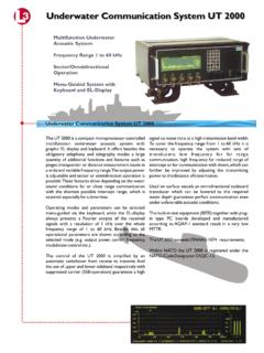
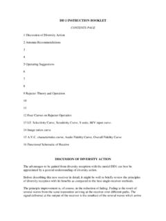
4 AM, FM, USB, LSB, CW and PA modes. The 10 most commonly used frequencies can be pre-programmed by the user for easy channel access. FEATURES RCI- 2985dx RCI- 2995dx 25 Watts PEP of Output Power Full Band Coverage All Mode Operation Brightness Control CTCSS Encoder/Decoder (Optional) Repeater/Offset Switch Programmable Frequencies Built-in Dual VFO RIT (RX Incremental Tuning) Squelch Noise Blanker RF Gain Control RF Power Output Selector External Speaker Connection PA Mode LCD Display Multi-Function LCD Meter 150 Watts PEP of Output Power Full Band Coverage All Mode Operation Brightness Control CTCSS Encoder/Decoder (Optional) Repeater/Offset Switch Programmable Frequencies Built-in Dual VFO RIT (RX Incremental Tuning) Squelch Noise Blanker RF Gain Control RF Power Output Selector External Speaker Connection PA Mode LCD Display Multi-Function LCD Meter - 4 -RCI- 2985dx RCI- 2995dx CHAPTER 3 OPERATION Figure 3-1 Front Panel INTRODUCTION This section explains the basic operating procedures for the RCI- 2985dx / RCI- 2995dx Amateur 10 and 12 meter dual band base station transceiver.
5 CONTROL AND CONNECTIONS FRONT PANEL Refer to the above Figure 3-1 for the location of the following controls. 1. POWER ON/OFF SWITCH Push this switch to apply power to the unit. 2. CALIBRATE CONTROL This control is used for calibrating the built in SWR meter for accurate SWR readout. Control should normally be left in the fully counter clockwise position for accurate power output meter readings. (This stop is marked RF ) 3. RF POWER CONTROL This control allows the user to adjust RF power output. 4. RF GAIN CONTROL This control is used to reduce the gain of the RF amplifier under strong signal conditions. $0 )0 66% $ H L 5 HKP 5& , ' Hz %H K 5) *$,1 6,*1$/7 &$/,%5$ 7(& PJH P , J 0,&523+21(32> (521 $,52))215) 5) 32> (56(7> $ 776 6> 5 0 /<$2' 64<(/&+ )5(4<(1&@0,& *$,1'? K% 2=(5 2,11% $1/',06>55 %((3&/$5,),(50(035*6&$163/,7(170$1/2&.)) ))))
6 6+) 02'(=2/<0($0)0<6%3+21(&>/6%3$ - 5 -5. MIC GAIN CONTROL Adjusts the microphone gain in the transmit and PA mode. This controls the gain to the extent that full talk power is available several inches away from the microphone. In the Public Address (PA) mode, the control functions as the volume control. 6. CHANNEL SELECTOR This control is used to select a desired transmit and receive channel. 7. CLARIFIER CONTROL Allows adjustment of the receive frequency above or below the channel frequency. Although this control is intended primarily to tune in SSB signals, it may be used to optimize AM/FM signals as well. 8. SQUELCH CONTROL This switch is used to eliminate background noise being heard through the receiver which can be disturbing when no signal is being received. To use this feature of your radio, gently turn the switch fully counterclockwise, and then turn clockwise until the background noise is just eliminated.)
7 Further clockwise rotation will increase the threshold level so that only strong signals will be heard. 9. VOLUME CONTROL Turn clockwise to set the desired listening level. 10. MODE SELECTOR This selector allows you to select one of the following operating modes: FM/AM/USB/LSB/CW/PA. 11. PHONE JACK Accepts a plug from a headset of 4 to 32 Ohm impedance. Insertion of the plug will disable the built-in speaker and external speaker connected to External Speaker jack. 12. RF/SWR METER Used for two purpose - to indicate approximate transmitter power when transmitting and antenna SWR (standing wave ratio). Note that the power meter has separate scales for AM, FM, SSB and CW transmission, respectively. 13. SIGNAL/MODULATION METER This meter indicates signal strength when receiving and modulation percentage when transmitting in the AM mode.
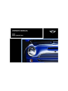
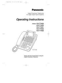
8 Modulation readings are most accurate when using maximum output power. The modulation meter does not show movement in FM or SSB, but the Power Output meter (RF/SWR) does indicate RF out in these modes. 14. FREQUENCY DISPLAY The frequency display indicates the frequency of the selected channel you wish to operate on. 15. FUNCTION INDICATORS The indicators permit you to know instantly the mode to which the unit is engaged. PROGRAMMING KEY PAD - 6 - 16. NB/ANL/OFF SWITCH In the NB/ANL position, the RF Noise Blanker and the Automatic Noise Limiter in the audio circuits are also activated. The Noise Blanker is very effective in eliminating repetitive impulse noise such as ignition interference. 17. ROGER BEEP BUTTON ( ) In the Roger Beep position, the radio transmits an audio tone at the end of your transmission to indicate that transmission has ended.
9 As a courtesy to others, use the Roger Beep only when necessary. 18. SPLIT BUTTON (SPLIT) This control activates the offset frequency function. It causes the transmit frequency to be offset either above or below the receive frequency by a user programmable amount to allow operation of a FM Repeater. 19. PROGRAM BUTTON (PRG) This button is used to program operating or scanning frequencies into memory. See the OPERATION section of the manual for further details. 20. MANUAL BUTTON (MAN) This is used to return the unit to manual mode. 21. SHIFT BUTTON (SHF) This is used to select 100 Hz, 1 KHz, 100 KHz or 1 MHz frequency steps. 22. UP/DOWN SELECTOR (VW) These buttons are used in conjunction with the shift key to move the frequency upward or downward to select a desired frequency. 23. LOCK BUTTON (LOCK) This button is used to lock a selected frequency.
10 Press it to activate the switch. In this position, it disables the Frequency Selector Control, up/down buttons on the front control panel and remote up/down buttons on the microphone. Repressing the switch will unlock the frequency. 24. ENTER BUTTON (ENT) 6+)/2&. 5 %((3 1% $1/',0 6> 5 35*0(0 63/,76&$1 0$1(17 - 7 -This is used to program memory channels. See the OPERATION section of this manual for more information on using this control. 25. MEMORY BUTTON (MEM) This button is used to program memory channels. Detailed information on how to use this control is provided in the OPERATION section of this manual. 26. SCAN BUTTON (SCAN) This is used to scan frequencies in each band segment. The OPERATION segment of this manual provides detailed information on using the SCAN control.)))