Transcription of READ AND SAVE THESE INSTRUCTIONS - tal-usa.com
1 read AND save THESE INSTRUCTIONSFAN RATING AC 120V. 60 HzUL LISTED MODEL : AC-552 MODEL# Y52YH5-06 CEILING FAN INSTALLATION ANDOPERATION INSTRUCTION2. PACKAGE CONTENTSU npack your fan and check the contents. You should have the following items;a. Fan blades (5)b. Hanger bracketc. Canopyd. Ball/downrod assembly (1) & extra downrod (1)e. Fan motor assemblyf. Set of blade brackets (5)g. Switch housingh. Light kiti. Glass shadej. Pull chain and fob (2)k. 60 Watt medium base bulbs (2) l. Package hardware 1) Mounting hardware : wire nuts(3) 2) Blade attachment hardware: screws(16) 3) Balance KitPhilips screw driverBlade screw driver11 mm wrenchStep ladderWire cutters11.
2 TOOLS AND MATERIALS REQUIRED abcdefghijlk1. To reduce the risk of electric shock, insure electricity has been turned off at the circuit breaker or fuse box before All wiring must be in accordance with the National Electrical Code and local electrical codes. Electrical installation should be performed by a qualified licensed WARNING: To reduce the risk of electrical shock and fire, do not use this fan with any solid-state fan speed control WARNING: To reduce the risk of personal injury, use only the two steel screws (and lock washers) provided with the outlet box for mounting to the outlet box. Most outlet boxes commonly used for the support of lighting fixtures are not acceptable for fan support and may need to be replaced, consult a qualified electrician if in The outlet box and support structure must be securely mounted and capable of reliably supporting a minimum of 50 pounds.
3 Use only CUL Listed outlet boxes marked "FOR FAN SUPPORT".6. The fan must be mounted with a minimum of 7 feet clearance from the trailing edge of the blades to the Do not operate reversing switch while fan blades are in motion. Fan must be turned off and blades stopped before reversing blade Avoid placing objects in the path of the To avoid personal injury or damage to the fan and other items, be cautious when working around or cleaning the Do not use water or detergents when cleaning the fan or fan blades. A dry dust cloth or lightly dampened cloth will be suitable for most After marking electrical connections, spliced conductors should be turned upward and pushed carefully up into outlet box.
4 The wires should be spread apart with the grounded conductor and the equipment-grounding conductor on one side of the outlet Electrical diagrams are reference only. Light kit that are not packed with the fan must be CUL Listed and marked suitable for use with the model fan you are installing. Switches must be CUL General Use Switches. Refer to the INSTRUCTIONS packaged with the light kits and switches for proper SAFETY RULESWARNINGTO REDUCE THE RISK OF FIRE, ELECTRIC SHOCK OR PERSONAL INJURY, MOUNT FAN TO OUTLET BOX MARKED "ACCEPTABLE FOR FAN SUPPORT".WARNINGTO REDUCE THE RISK OF PERSONAL INJURY, DO NOT BEND THE BLADE BRACKETS (ALSO REFERRED TO AS FLANGES) DURING ASSEMBLY OR AFTER INSTALLATION.
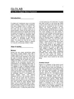
5 DO NOT INSERT OBJECTS IN THE PATH OF THE MOUNTING OPTIONSIf there isn't an existing CUL listed mounting box, then read the following INSTRUCTIONS . Disconnect the power by removing fuses or turning off circuit the outlet box directly to the building structure. Use appropriate fasteners and building materials. The outlet box and its support must be able to fully support the moving weight of the fan (at least 50 lbs). Do not use plastic outlet 1,2 and 3 are examples of different ways to mount the outlet : You may need a longer downrod to maintain proper blade clearance when installing on a steep, sloped ceiling. (Fig. 3)Outlet boxProvide strongsupportRecessedoutlet boxCeilingmountingplateOutlet boxFigure 1 Figure 3 Figure 4 Outlet boxFigure 23 Angled ceilingmaximum20o angleREMEMBER to turn off the power.
6 Follow the steps below to hang your fan properly:Step 1. Pass the 120-volt supply wires through the center hole in the ceiling hanger bracket as shown in Fig. 2. Secure the hanger bracket to the ceiling outlet box with the screws and washers provided with your outlet 3. Remove the hanger pin, lock pin and set screws from the top of the motor 4. Route wires exiting from the top of the fan motor through the canopy and then through the ball / downrod. (Fig. 6)Step 5. Align the holes at the bottom of the downrod with the holes in the collar on top of the motor housing ( ). Carefully insert the hanger pin through the holes in the collar and downrod.
7 Be careful not to jam the pin against the wiring inside the downrod. Insert the locking pin through the hole near the end of the hanger pin until it snaps into its locked position. (Fig. 6) Step 6. Tighten two set screws on top of the fan motor firmly. (Fig. 6)Step 7. Place the downrod ball into the hanger bracket socket. (Fig. 7)CHANGING THE DOWNROD (OPTIONAL)NOTE: Your fan comes with a 4" downrod attached to the hanger ball. In addition you have been provided with a 6" downrod to use if desired. If you choose to use the 6" downrod, perform the following Remove the hanger ball from the 4" downrod by loosening the set screw at the top of the downrod which holds the hanger ball to the Slide the hanger ball down the downrod and remove the support Insert the support pin in the holes at the top of the 6" downrod and slide the hanger ball up the 6" downrod.
8 Make sure the support pin is properly seated in the grooves in the top of the hanger Tighten the set screw Hanging the Fan4 Mounting screws (supplied with electrical box)Hook HangerbracketUL Listed electrial boxFigure 5 Figure 6 Figure 7120V WiresWashersRegistration slotDownrodCanopySet screwsHitch pinLock pin56. MAKE THE ELECTRIC CONNECTIONSR emember to disconnect the the steps below to connect the fan to your household wiring. Use the wire connecting nuts supplied with your fan. Secure the connectors with electrical tape. Make sure there are no loose strands or 1 Connect the fan supply (black) wire and light supply (blue) wire to the black household supply wire as shown in Figure 2.
9 Connect the neutral fan (white) wire to the white neutral household 3 Connect the fan ground wire (green) to the household ground 4 After connecting the wires, spread them apart so that the green and white wires are on one side of the outlet box and the black and the blue wires are on the other 5 Turn the connecting nuts upward and push the wiring into the outlet box. Figures 9 and 10 illustrate the wiring connections for optional wall control. (The wire color out of wall control may vary, see wall control's installation manual for correct wire connections.)NOTE: LIGHT KITS ARE AVAILABLE AT YOU SAVOY HOUSE RETAILER. THE FAN IS ALREADY WIRED TO SUPPORT THE LIGHT KIT : TO REDUCE THE RISK OF FIRE, ELECTRIC SHOCK, OR OTHER PERSONAL INJURY.
10 MOUNT FAN ONLY ON AN OUTLET BOX OR SUPPORTING SYSTEM MARKED "ACCEPTABLE FOR FAN SUPPORT". Figure 8 Figure 9 BLKWHBLUE BLKWHGRNWIRINGBOXWIRINGBOXGROUND TOMOUNTINGBRACKETOR DOWNRODGROUND TOMOUNTINGBRACKETOR DOWNRODBLUEBLKWHWHFANLIGHTPOWER LINES 120 VPOWER LINES 120 VBLKWHBLUE BLKWHFANLIGHTBLKBLUEWHWHLIGHTSWITCHGREEN GROUNDGREEN GROUNDF igure 10 GROUND TOMOUNTINGBRACKETOR DOWNRODPOWER LINES 120 VGREENGROUNDWIRINGBOXBLKWHBLUE BLKWHFANLIGHTWHWHBLUEBLKLIGHTFAN67. FINISHING THE INSTALLATIONStep 1. Slide the canopy up to the ceiling and over the two screws on hanger bracket. Rotate canopy clockwise until : adjust the canopy screws as needed until the canopy is snug.