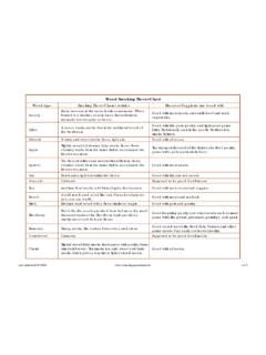
Transcription of realised with Resistor Varistor RC-circuit
1 80 Arc extinguishing, arc suppressionIf the upper limit of the arcing voltage which depends on the switching current and contact material is exceeded, the relay contact dischargescurrent, leading to material degradation in the contacts. To ensure that contacts perform reliably over a long service life despite this unfavourablephenomenon, circuitry must be designed to include measures to suppress arcing for a given ( s)Course of voltage at relay contactwith inductive loadVoltage (V)GlowshowerArc10mA234568100mA1nF234568 1A23456810A24610nF2460,1 F2461 F24610 F5122030607,51015245080100200500246810 1 2468100 24681k 246810k RCURCIUArc suppression with RC-circuitDiagram for determining optimum valuesConsumerExample: U = 100V I = 1 AThe value for C is 0,1 F(Point of intersection with R = 10 )Arc suppressionrealised withResistorVaristorRC-circuitDiagramCou rse of currentat loadCourse of voltageat loadCourse of voltageat switchAdvantagesRelatively shortSmall overvoltagerelease delayshort release delayDisadvantagesRelatively longNot for allrelease delayapplicationsRRLLiUB0123tiUBU013tUBU 013tRLLiUB0123tiUBU013tUBU013tVRRLLiUBC0 123tiUBU013tUBU013tUBU013tUBU013t0123tiD RLLiUB+-UBU013tUBU013t0123tiRRLLiUB+-DUB U013tUBU013t0123tiZRLLiUB+-DArc suppressionDiode + Diode + realised withDioderesistorZener diodeDiagramCourse of currentat loadCourse of voltageat loadCourse of voltageat switchAdvantagesSmallOvervoltage andSmall overvoltage,overvoltagerelease delay depends on Rshort release delayDisadvantagesRelease delayRelease delayvery longlong243 Naugatuck.
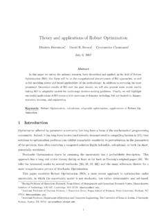
2 CT06460 INFORMATIONE arlyfailuret1mt2tFailure dueof wearRandom failureFailure rate 1 = MApprovalsApprovals are copyright protected marks of institutes charged withtesting components. Once a product or process has been awarded theapproval after testing and evaluation, the manufacturer may affix thecorresponding certificate of approval to his product or soldering line proofAutomated soldering line proof relays are suitable for both automatedand hand soldering. However, in flux and rinsing processes, the relaysmay not be immersed. Caution is also in order when cleaning agentsare used. Here residue may damage the relays. These relays are oftencalled dust-proof .Bathtub curveCommon term for the curve that describes the expected failure rate ofelectronics with time. Initially high, it drops to near 0 for the majority ofthe system s lifetime and rises again as it wears )Early failure: Here the failure rate has a distinctly )Random failure: Within this range, the failure rate is constant; thisrange is generally described as its service life.
3 C)Failure due to wear: Here the failure rate increases as the component and material Bouncing occurs primarily when an electromechanical contact closesand the kinetic energy stored in the moving part of the contact isreleased, causing the part to bounce back and sever the this process, which is often called chatter, is repeated severaltimes at briefer intervals as the bouncing distance decreases. The subsequentcontact tremor (oscillating contract force) is not considered as part ofthe bouncing process it is actually part of the dynamic contactresistance or decay phaseBounce timeAccording to DIN 41215, bounce time is the time elapsed between thefirst to the last opening or closure (make or break) of a relay contactwhen a relay is switching from one status to the other. The pick-up anddrop off phases are not included in the bounce is material degradation induced by switching contact currentThe value of the current which can be continuously applied to the relaycontacts within the permissible temperature rise type by typeSingle-Pole Single ThrowSwitch with only one moving and onestationary contact.
4 With this type of relaycontact, a single pole contact isresponsible for establishing Pole Single ThrowA double pole consists of two contactsthat operate in parallel. This enhances thecontact reliability and is primarily used toswitch low current and voltage circuits(dry circuits)Cross contactThese rail-shaped contacts areperpendicular to each other at a 90 angle to form a contactThe ring of this type of contact closes attwo slightly offset points. Through arelatively high amount of pressure onthese points, the contact force is able topenetrate dust and debris. The contact isself-cleaning. by type of manufactureRiveted contactThe contact terminal is riveted to thecontact contact The contact terminal is welded to thecontact carrier. by function (basic forms)Normally open contact ( ) The condition of this type of contact in itsnormal (unenergised) state.
5 When thecontact is energised, the circuit is closed contact ( ) The condition of this type of contact in itsnormal (unenergised) state. When thecontact is energised, the circuit is contactA switching contact whereby the normallyclosed contact breaks before the normallyopen contact makes. Contact make243 Naugatuck , CT06460 forceContact force is the force that the contact components exert on eachother is a closed springsThe majority of relays feature contact springs. These are subjected tomechanical, thermal and electric loads. It is essential that heatgenerated by flowing current and arcing does not unduly influence theperformance of the out currentDrop current is a peak current that flows through a relay and coil to de-energise it and break the service lifeThe life of a relay when it is switched at the rated operating conditions(maximum switching frequency, contact resistance, make and breakvalues, insulation resistance etc.)
6 With the rated load applied to itscontacts at a performance probability of 95%.Contact materialsthermalspecificMaterialDescript ionMeltingBoilingHardnessconductanceelec tricalelectricalDensitypointpointsofthar dat 20 Cconductanceresistance[g/cm3][ C][ C][HV][HV][W/(K x m)][m/( x mm2)][( x mm2)/m]AgNi0,15 Fine silver10,5960220055100415580,017 AgCuNiHard silver10,4940220070115385520,019(Argodur )AgCu3 Hard silver10,4900-22008016037247,6 (soft)0,021 (soft)93843,40,023 AgCdO10 Silver10,2961220070110307480,021cadmium oxideAg-shareAgSnO2 Silver9,9961220070110*490,02010 Ptin oxideAg-shareWTungsten19,334105930 13018,180, plating**AgNi10 Silver nickel10,396122005090350540,01810Ag-shar eCreeping and leakage distance Creeping and leakage distances are safety spaces or margins betweenall of the current carrying components as well as between currentcarrying and non-current carrying grounded components.
7 These aregenerally defined as follows:Leakage distanceis the shortest direct distance between two points the air distanceis the shortest distance between two points alongthe surface of an insulation material. This distance between two pointscan be increased by incorporating channels or grooves in the strengthElectric strength or voltage stability describes the voltage which can berouted to two electrodes that are insulated from one another withoutcausing a discharge. Voltage stability depends on the following factors: Thickness and purity of the insulation material Loss angle of the insulation material Temperature and duration of the effect Humidity Array of the electrodesForcibly guided contactsContacts can be guided forcibly when they are connected mechanicallyso that the make and break contacts cannot be closed at the sametime. For this type of setup, that contacts maintain a distance of atleast mm over the entire service life, even under flawed flashingGold flashing does not fully cover the contact (layer thickness less m) and serves to protect a contact during storage.
8 The layer isporous and thus the protective benefits of gold flashing iscontroversial. Gold flashing is irrelevant to the switching performanceof a gold plating Hard gold plating is a layer that covers the basic material of a contactfully in a thickness of 2 m (4 6 m at ELESTA). It prevents corrosion ofa contact and is used for switching small loads (dry circuits) where noor minimal arcing Naugatuck , CT06460 proof / sealedImmersion proof relays can be subjected to a rinsing process. Incompliance with the manufacturer s stipulations, no cleaning agentsmay penetrate to the interior of the relay. Immersion proof relays alsoprovide good protection against dust, particles and waste current The peak value of a current which a load requires when first beingenergised. It is essential to take the intensity and duration of inrushcurrent into account for certain types of loads when capacitors orlamps be installed in the circuit.
9 These will draw a substantially largerinitial current than carry resistanceInsulation resistance is the smallest amount of resistance offered by aninsulating material. It is measured at 500V between insulated parts viaohm meter or galvanometer. If the contacts feature substantially betterinsulation from the coil or a grounded non-current-carrying part, thenthis is annotated in the relay ratingsRelay contacts are generally rated for five different loads, which arelisted under items a) through e).The load rating g) is reserved for contactors. For the load rating f),there is no clear-cut dividing line between a relay and a contactor; inother words, the value is not defined following table defines the voltage and current limits for theseseven load range ratings. In this case, the current values apply to thecontact load on make and break rather than the thermal limiting ) Dry circuits b) Low level circuits c) Minimum current circuits (short arcs may occur here)d) Intermediate level circuits e) High level circuits (stable arcs are typical here)f) Low power contacts g) Power contacts Area of stable arcsArea of short arcsUpper limit is the meltingvoltage USUpper limit is the softeningvoltage UEU>300 U>10V U<10V U<10V U<300mV U<100mV<1kV <300VI<10mAbaI<100mAcI<300mAd*I<10 AeI<50 AfI>50Ag* I = 50 to 400 mA, U = 28 V direct currentMagnet systemA magnet system comprises all parts of a magnetic circuit that have afunction in determining its consists of a.
10 1) Coil core2) Coil3) Yoke4) Actuator armMechanical service lifeThe life of a relay in terms of its mechanical functions when it isoperated at room temperature and at the maximum mechanicaloperating frequency without applying a load to its contacts while allspecifications and operating prerequisites are relaysA monostable relay is a two position relay. If it is equipped with achange over contact, the NC spring is closed in the unenergised positionThis describes the position that a relay must be mounted in to ensureflawless operation. All ELESTA relays can be mounted in any value (nominal voltage, nominal current, nominal energising (make or break), nominal power)Other relay-related specifications are assigned to the nominal value. Forexample, rise time is indicated for the nominal voltage rather than thepick-up voltage (make or break voltage). Generally, the nominal value isequivalent to the operating value.