Transcription of Recommendations for welding of - HIGH STRENGTH
1 Recommendations for welding of Tk Steel 1. General ThyssenKrupp Steel produces heavy plates for wear-exposed structures under the trade name XAR . These steels are mainly used for excavating, mining and earth-moving machinery, conveying and cru-shing equipment and other machinery. For moderate wear a hardness of about 300 HB can be achieved via normalizing rolling. For higher wear resistance steels with hardnesses from 400 up to 600 HB have been developed. They exhibit a special chemical composition combined with a heat treatment by quenching or quenching and tempering. Due to their alloying and high hardness, certain measures have to be taken into account to ensure reliable welding .
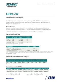
2 XAR 400 and XAR 450 are the standard wear-resistant steel grades which have the most pro-cessing-friendly chemical composition with relatively low carbon equivalents. Carbon equivalents for thicknesses up to 35 mm CEV, typical [%] CET, typical [%] Steel grade t 8 mm 8 - 35 mm t 8 mm 8 - 35 mm XAR 300 XAR 400 XAR 450 XAR 500 XAR 600 The susceptibility of steels to cold cracking can be estimated on the basis of their chemical composition. Particularly suitable for this is the carbon equivalent CET derived from extensive cold cracking tests. The relevant research work conducted by ThyssenKrupp Steel AG on the avoidance of cold cracking has led to the CET concept and its adoption in EN 1011-2.
3 Calculation of carbon equivalentsIIW- formulaCET- concept (EN 1011-2, Annex )15 NiCu5 VMoCr6 MnCCEV++++++=40Ni20 CuCr10 MoMnCCET+++++=2. Weld seam preparation The welding zone has to be cleaned. Scale, rust or residual paint have to be removed by brushing or grinding. Also, it must be ensured by drying or pre-heating that the welding zone is free from any humi-dity. The weld edges should be checked by visual inspection, or by means of a dye penetrant tech-nique, for cracks and other defects that might impair welding such as slag residues. 3. welding filler metals The risk of cold cracking occurring in the weld metal can be minimized by using austenitic welding filler metals.
4 If ferritic welding filler metals are used for cost rea-sons, preference should be given to the MAG solid wire, as it offers appreciable advantages because of the comparatively low hydrogen content in the weld metal. A soft, unalloyed weld metal (yield STRENGTH below 500 MPa) that has good ductility is also prefer-able. This applies especially to comparatively thin plates or fillet welds, because here the weld metal is diluted by the higher-alloy parent metal. For butt welds or multi-layer fillet welds, an increased yield STRENGTH is sometimes required in the weld region of wear-resistant components. In such cases a medium alloyed welding filler metal (yield STRENGTH of weld metal from 500 to 700 MPa) can be used for filling and capping passes.
5 Recommendations for welding of Page 2 Solid wires forMAG-weldingEN ClassificationAWS ClassificationausteniticG 18 8 Mn ( )according to EN 12072ER307acc. to AWS A ,Re < 500 MPa G 46 4 M G4Si1 orG 50 5 M G3Ni1according to EN 440ER70S-6 orER80S-Gacc. to AWS A ,500 - 700 MPaG 62 5 M Mn3Ni1Mo orG 69 5 M Mn4Ni1,5 CrMoaccording to EN 12534ER90S-G orER100S-Gacc. to AWS A To avoid cold-cracking it must be ensured that the hydrogen content of the welding material is as low as possible. Therefore, the welding filler metals have to be protected against any absorption of moisture. The basic covered electrodes and welding flux have to be post-dried in accordance with the manufacturer's instructions immediately before use.
6 Afterwards the covered electrodes have to be stored at 100 C to 150 C until they are used for welding . Other welding consumables which have not been listed here can also be used. The selection is not exclusive and should not be taken as any deprecation of the suitability of other filler HLERESABLINCOLNOERLIKONTHYSSEN austeniticA 7 CN-IGOK Autrod 307 Inertfil 18 8 6 Thermanit Xferritic,B HLER EMK 8 LNM 27 CARBOFIL 1 aUnion K 56Re < 500 MPa B HLER DMO-IGLNM Ni 1 CARBOFIL 2,5 NiUnion K5 Niferritic,LNM NiMo1 CARBOFIL NiMo 1 Union MoNiRe = 500 - 700 MPa*LNM MoNiVaCARBOFIL NiMoCr Union NiMoCrDrahtzug SteinESABLINCOLNOERLIKONTHYSSEN austenitic-OK Tubrod (Cor-A-Rosta 307)
7 Fuxinox 307 PFThermanit TG 307ferritic,Outershield MC 715-HUnion BA 70Re < 500 MPa Outershield 81Ni1-HUnion MV 70ferritic,OK Tubrod 81K2-HRe = 500 - 700 MPa*OK Tubrod 690-HB HLERESABLINCOLNOERLIKONTHYSSEN austeniticFOX A 7 CNOK 307 CITOCHROMAX NThermanit Xferritic,Conarc 49 CRe < 500 MPa Kryo 1ferritic,Conarc 60 GPhoenix SH V 1Re = 500 - 700 MPa*Conarc 80 Phoenix SH Ni 2 K 100B HLERESABLINCOLNOERLIKONTHYSSEN ferritic,Re < 500 MPa ferritic,Re = 500 - 700 MPa*3 NiMo 1-UP3 NiCrMo 2,5-UP/B hler BB 24OK Autrod /Flux 164 LNS 168 /Lincolnweld 8500OE-S3 NiMo1OE-S3 NiMo2 /OP 121 TTUnion S 3 NiMoUnion S 3 NiMoCr /UV 421 TTRe = minimum yield STRENGTH of weld metal *) not recommended for XAR 600 Solid wires for MAG- welding (shielding gas M 21)
8 TENACITOP hoenix 120 KFOX EV 65 FOX EV 85OK 65 RFluxofil 41OK Tubrod S 2 Mo / UV 421 TTType of weldingfiller metalManufacturerOK AristoRod HLER NiMo 1-IGB HLER X 70-IGOK AristoRod MV NiMoCrCovered electrodes for manual metal-arc weldingManufacturerMegafil 731 BMegafil 240 MFluxofil 31 Megafil 740 BMegafil 742 BEMS 2 /B HLER BB 24 LNS 135 / P230 LNS 133U / P230OE-S2Mo / OP 139 Type of weldingfiller metalFlux-cored wires for MAG- welding (shielding gas M 21)Type of weldingfiller metalFOX EV 50OK Autrod /OK Flux / fluxes for submerged arc weldingType of weldingfiller metalManufacturerRecommendations for welding of Page 3 4. Avoidance of cold cracking The avoidance of cold cracking requires special con-sideration for all the wear-resistant steels.
9 Cold cracking is a time delayed phenomenon in the heat-affected zone or in the weld metal that can occur under conditions of hydrogen and stress exposure. An effective means for avoiding such cracking is preheating. It delays the cooling of the weld region and can thereby provide a hydrogen effusion. Measures to ensure a minimum input of hydrogen in the weld metal, such as cleaning and drying of the weld grooves, stable flow of shielding gas during MAG welding , and use of redried basic coated elec-trodes for manual arc welding , are also necessary. The welding sequence should be chosen with respect to minimized residual stresses. If XAR steels are welded with austenitic welding filler metals, generally there is no preheating neces-sary.
10 The parts to be joined should have room temperature (at least 15 C). For XAR 600 with plate thicknesses above 25 mm, it is recommended to preheat to 100 C - 150 C when welding with aus-tenitic consumables in order to take into account the stresses to be expected in the welding zone. If ferritic consumables are used, sufficient prehea-ting of the welding zone is required in many cases. Until the weld joint has been completed, the temperature should not fall below the preheating temperature. Taking into account the mechanical properties of the base material, preheating tempera-tures and interpass temperatures in excess of 200 C should be avoided.