Transcription of Reduction of the High-Frequency Switching Noise …
1 AN1466. Reduction of the High-Frequency Switching Noise in the MCP16301 high - voltage Buck Converter This application note will discuss circuit design and Author: Valentin Constantin layout techniques used to significantly reduce this Microchip Technology Inc. Noise to an acceptable level, using the MCP16301 as an example. MCP16301 is a highly-integrated, high -efficiency, fixed- frequency step-down DC-DC. INTRODUCTION converter in a popular 6-pin SOT-23 package, that When developing high -input voltage DC-DC buck operates from input voltage sources up to 30V. converters, there is a trade-off that has to be made between efficiency and size. For devices with an integrated switch, driver and control system, there are still some design changes that can be used to optimize the design for specific applications.
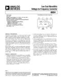
2 The MCP16301. integrated MOSFET was developed to maximize efficiency resulting in high , very fast turn on and off of the integrated N-Channel MOSFET. Depending on the number of layers of the printed circuit board and external components chosen, some High-Frequency Noise will be present in the output voltage and input voltage and can have a negative impact for some designs. 1N4148. CBOOST L1 VOUT. VIN 100 nF 22 H. BOOST 5V @ 600 mA. 6V to 30V SW. VIN 40V COUT. Schottky 2 x 10 F. CIN Diode 2 x 10 F EN k . VFB. GND 10 k . FIGURE 1: Typical MCP16301 Buck Converter Application. 2013 Microchip Technology Inc. DS01466B-page 1. AN1466. MCP16301 DEVICE SHORT Detailed information is available in the MCP16301 data sheet (DS25004), [1]. OVERVIEW. The MCP16301 is a high input voltage step-down regulator, capable of supplying a maximum of 600 mA.
3 RIPPLE AND Noise IN BUCK. to a regulated output voltage from to 15V. An CONVERTERS. integrated, precise reference, combined with an Step-down converters use higher Switching frequency external resistor divider sets the desired converter to take advantage of smaller inductor and input and output voltage . The internal reference voltage rate of output ceramic capacitors. But Switching at high fre- rise is controlled during start-up, minimizing the output quency generates another problem for an entire power voltage overshoot and the inrush current while soft system: Switching Noise . This Switching Noise is a result starting the output voltage . of the fast Switching edges of the integrated N-Channel Internally, the trimmed 500 kHz oscillator provides a MOSFET and is typically in the hundreds of MHz.
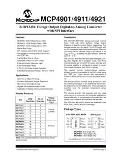
4 Fixed frequency , while the Peak Current Mode Control architecture varies the duty cycle for output voltage regulation. An internal floating driver is used to turn the high -side integrated N-Channel MOSFET on and off. The power for this driver is derived from an external boost capacitor, whose energy is supplied from a fixed voltage (between and ), typically the output voltage of the converter. For applications with < VOUT < , boost supply can derive from the input, output or an auxiliary system voltage (more infor- mation and examples can be found in the MCP16301. data sheet (DS25004), [1]). The enable input (EN) is used to enable and disable the device. If disabled, the MCP16301 device consumes a minimal current from the input (quiescent current in FIGURE 2: The Two Noise Components shutdown is typically 7 A).
5 A logic high (> ) will for a Buck Converter. Example for 12V Input, enable the regulator output. A logic low (< ) will 5V Output and 100 mA Load Using MCP16301. ensure that the regulator is disabled. Without Any Noise Reduction Techniques. An integrated Under voltage Lockout (UVLO) prevents Switching converters' input/output ripple and Noise can the converter from starting until the input voltage is high reach levels high enough to interfere with other devices enough for normal operation. The converter will powered from the same source. typically start at and operate down to There are two Noise sources: When the device is Switching at no load, the current drained from the power supply is approximately 2 mA. Output Ripple occurs at the fundamental switch- ing frequency Overtemperature protection limits the silicon die Switching Noise is associated with high temperature to +150 C by turning the converter off.
6 The frequency ringing that occurs during on-off normal Switching resumes at +120 C. transition of semiconductor switches. This type of A typical 5V buck converter from 6 to 30V input, using Noise is hundreds of MHz and up to hundreds of the MCP16301 device, is shown in Figure 1. It uses a mV peak value (Figure 2). ceramic capacitor for input and output, a small 22 H. Noisy components require separate filtering. The low- inductor, sense resistors for feedback and a rectifying frequency output ripple of the MCP16301 is generally Schottky diode. The diode should be connected close 20 mV peak-to-peak, and it depends on the output to the SW node and GND. The 1N4148 boost diode capacitor value and capacitor dielectric type. Low ESR. and boost capacitor are used to bias the internal driver and ESL ceramic capacitors significantly decrease the for the main switch, as described above.
7 Output- voltage , low- frequency ripple. The output ripple The input source should be decoupled to GND with a is easy to reduce, using a low ESR and ESL ceramic F-20 F capacitor, depending on the impedance capacitors (X7R or X5R-type). Switching Noise requires of the source and the output current. The input capaci- more attention. Overall, there are a couple of simple tor provides current for the switch node and a stable methods to reduce the Noise . This document focuses voltage source for the internal device power. This on how the Switching Noise can be reduced for a capacitor should be connected as close as possible to MCP16301 buck converter. the VIN and GND pins. For light-load applications, a 1 F X7R or X5R ceramic capacitor can be used. DS01466B-page 2 2013 Microchip Technology Inc.
8 AN1466. Reduction OF THE high Why Additional Output Capacitance frequency Switching Noise Does Not Help? The MCP16301 operates at a high - Switching frequency Generally, ceramic capacitors significantly decrease (500 kHz, typical). If the target application using the output voltage low- frequency ripple. But additional MCP16301 requires high efficiency and a low- output capacitance does not remove the high - Switching Noise , additional components and a good frequency Noise . Ceramic capacitors have high - PCB design practice will sufficiently reduce that Noise impedance in the frequency band in which this Noise to an acceptable level. occurs. The ringing frequency is very high (see Figure 5), and the output capacitor alone or an extra Measuring Output Ripple and Noise low-value capacitor in parallel with it are ineffective in attenuating this Noise .
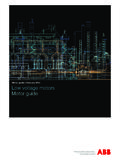
9 Figure 4 shows exactly why a Correctly small capacitor is ineffective in attenuating Noise on The output ripple is millivolts peak-to-peak (mVp-p) and today's converters. Even if the impedance is lower at requires special attention when measuring. Accurate high frequency , the value is not sufficient to reduce the results are obtained when the measurement is taken as ringing. closely as possible to the output capacitor. The total loop area in the signal and ground connections has to Impedance vs. frequency - X7R. be small. To minimize the area, remove the ground lead 10000. F. of the scope probe and measure the output capacitor 1000 F. Impedance ( ). voltage differentially, using a short wire wrapped on the 100. ground body's scope probe (barrel), close to the tip's probe.
10 10. 1. 1 10 100 1000. frequency (MHz). Wire on GND. Barrel FIGURE 4: Variation of Impedance with Capacitor Value in the frequency Band for an X7R Capacitor. Using an RC Snubber Using an RC Snubber to remove the High-Frequency Probe tip Noise is a well-known method. It requires a minimum of mathematics to get a good estimation of the snubber's SMD Output resistor and capacitor values, and some knowledge on Capacitor the parasitic values of the Switching elements. high - frequency ringing is generated by the parasitic FIGURE 3: Correct Measurement of the elements of the converter's power stage. Typically, this ringing runs above hundreds of MHz and it repeats Output Ripple/ Noise Using an Oscilloscope itself at each Switching cycle (Figure 2). Probe. To determine the values of the Snubber circuit, follow The test is done with an oscilloscope, properly the steps: calibrated to avoid errors.