Transcription of Reflow Profiling: Timea bove Liquidus
1 Reflow Profiling: Time a bove LiquidusAIM/David Suraski Despite much research and discussion on the subject of Reflow profiling, many questions and a good deal of confusion still exist. What is clear is that the pains often associated with profiling can be reduced if there is a strong understanding of the variables that can be encountered during the Reflow process, as well as the metallurgical dynamics of the soldering process. This paper shall provide a brief outline of the Reflow profile in general, with specific emphasis placed upon the suggested time spent above the melting temperature of the solder.
2 The guidelines for soldering to various surfaces and with alternative solder alloys also are discussed. General Reflow Guidelines While varying Reflow profiles may be utilized to achieve optimum soldering results, in general these share many of the same details. For the Sn63/Pb37 and Sn62/Pb36/Ag2 alloys, the typical profile length is 3 to 4 minutes from the time the assembly begins to heat up until it reaches its maximum temperature of 215 C 10 C. The assembly is reflowed above the Liquidus point of the solder (183 C for Sn63, 179 C for Sn62) for a target time of 60 seconds 15 seconds.
3 It should be noted that this time above Liquidus is measured not only during the profile s rise, but also during its cool-down. The cool down rate of the profile should be controlled within 4 C per second. In general, a faster cool down rate will result in a finer grain structure and a stronger and shinier solder joint. However, exceeding 4 C per second could result in thermal shock to the assembly. Reflow Dynamics- Intermetallics The goal of the soldering process is to form an intermetallic layer between the solder and the circuit board and the solder and the component. Simply explained, an intermetallic is a combination of the base metals with the solder that provides the mechanical and electrical integrity of the solder joint.
4 However, as most frequently used in soldering, the term intermetallic is often used as an abbreviation for intermetallic crystal (IMC), which refers to a specific class of materials. As discussed below, it should be noted that IMCs are a problem of soldering and can lead to long-term When soldering to a copper substrate with tin/lead solder, two types of IMCs are formed. The copper -rich Cu3Sn intermetallic, which melts at 670 C, is found near the substrate, while the tin-rich Cu6Sn5, which melts at 415 C, is found throughout the joint. As the melting temperatures of these are significantly higher than soldering temperatures, they will not be melted during the Reflow process and thus will remain in the joint as occlusions.
5 During soldering, the intermetallic crystals are precipitated out. This intermetallic will continue to form at a slower rate in the solid phase. The growth as a 1 Manko, Howard. Solder and Soldering. Third Edition, 1992, McGraw Hill. p. 98 solid is driven by temperature; as the solder approaches its melting point, the rate of intermetallic growth increases. Most growth does not amount to much below 125 C, but at 150 C the intermetallic growth is logarithmic to the temperature increase. It is for this reason that high-tin Sn/Pb systems should not be utilized to assemble that devices that operate above 150 C for extended times and that it is recommended to stay below 250 C during soldering.
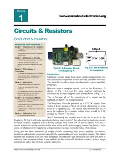
6 The dissolution rate of copper at various temperatures is shown in the chart below. Temperature C Dissolution rate um/s Dissolution rate 250 .47 275 .70 300 .88 350 To prevent the reactions between solder and copper , a layer of less-reactive metal can be used as a barrier. Nickel is used extensively for this purpose as a barrier plating, as there is very little formation of intermetallic compounds during the tin- lead soldering process. Iron also is used, albeit far less extensively, for this purpose. Time above Liquidus and Delta T The goal of achieving the target time above Liquidus is to achieve optimal solder spread on solder joints across the circuit board.
7 Other benefits are to reduce flux entrapment and voiding and increase pull strength. Generally, solder Liquidus times of 30 to 60 seconds are preferable, although Liquidus times of 90 seconds or more are not uncommon on larger boards. This is due to the potential of a large Delta T of an assembly with a large variation of thermal mass. Delta T is defined as the greatest differenc e of temperature found across a circuit board. The result of a large Delta T is that some areas of an assembly heated could reach much higher temperatures than other areas. Therefore, in order to ensure that all parts of an assembly reach the minimum requirements of time above Liquidus ( , 30 seconds), the more rapidly heated areas may be exposed to the upper limits (90 seconds) of time above Liquidus .
8 Solder Spread & Wetting Angle The solder spread and wetting angle of a solder joint are the most pertinent visual inspection criterion for a properly reflowed assembly. Greater solder spread and a lower solder joint angle are indicative of a properly reflowed, and therefore more durable, solder joint. In general, a solder joint angle of 75 or less is desirable. Ideally, the solder is feathered out, indicating a small dihedral angle. In addition, the solder joint will appear bright and smooth, with few or no pinholes. As discussed above, the time above Liquidus necessary to achieve adequate wetting appears to be in the range of 45 to 90 seconds.
9 If the solder is above the Reflow temperature for too short a time, there is the risk that marginal or non-wetting will occur, which will have a deleterious effect upon solder joint reliability. In pull tests, solder joints exposed to lower times above Liquidus tend to have higher failure rates. Excessive Time Above Liquidus Reliability-related issues also can occur if the solder is above Reflow temperature for too long a time. During the soldering operation the molten solder will dissolve the metallization and/or the base contact metal and precipitate intermetallics that will form the bond responsible for giving the solder joint its strength.
10 If the metallization dissolves too rapidly or is too thick the integrity of the solder joint can be compromised by forming too large a volume fraction of the intermetallic phase. Once a joint develops a coherent layer of intermetallic compounds, it loses its metallic properties and becomes brittle, and any subsequent shock or stress to the joint can lead to failure2. In a comparative test, solder joints were reflowed for 60, 90 and 120 seconds above Liquidus . As is shown below, the intermettalic layer increased significantly with each incremental increase in time above Liquidus .