Transcription of REFRIGERATION CYCLE
1 CRYOGENICS 8/25/04 REFRIGERATION CYCLEThe REFRIGERATION CYCLE shown here is a typical R-22 system. The compressor andthermal expansion valve are the boundaries for the high and low 's important to understand that a refrigerator is a heat engine that operates inreverse. Energy is transferred from a low level to high level, which is contrary tothe spontaneous processes that occur in nature. To accomplish this transfer , anamount of work must be supplied dependent on the temperatures must be added to this workload to compensate for the inefficienciesinherent in heat transfer , inefficiencies that arise from heat exchange equipmentand the irreversible behavior of compression or expansion of the same principles used in this basic system apply to normal cryogenicrefrigeration systems as BASIC SYSTEMCOMPRESSORThe compressor takes low pressure, low temperature gas and compresses it intoa high pressure, high temperature Primer2 CONDENSORThe condenser accepts the gas from the compressor and, through some coolingmedium, condenses it to a high pressure.
2 Cool temperature EXPANSION VALVEThe liquid line feeds the thermal expansion valve or device where the liquidexpands and flashes to a gas and evaporator is a heat exchanger where the expanded cold gas exchanges heatwith the area being cooled. (This area may be a refrigerator, your living room, ora meat locker. The fluid generally is just normal air.)CARNOT CYCLEAll refrigerators work on a combination of processes, cycles, which achievecooling, and thereby liquefaction, through expansion. The Carnot CYCLE is acombination of isentropic and isothermal Expansion, is where a fluid does work and expands keeping itsentropy constant. This is an adiabatic process; no heat is allowed toenter or leave the system.
3 It is also a reversible process since thework can be returned to the fluid through compression. This is thebest method of expansion because it produces the largesttemperature change over a given pressure. (Van Sciver 273, Sears348)Isenthalpic Expansion, is where a fluid undergoes a pressure changewithout heat transfer . This method is in common application inpractical REFRIGERATION systems for its ease of use. However, it is oflower thermodynamic efficiency because it is an irreversibleprocess leading to Carnot, (1796-1832) a French physicist and engineer, developed, in 1824, ahypothetical heat engine with a 100% efficiency. (As we learned earlier, this iscontrary to the second law.)
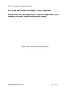
4 He examined this hypothetical engine anddiscovered that the perfect engine must avoid all irreversible processes. Everyheat transfer , in his idealized CYCLE , must be isothermal or formula K = TC /TH TC, represents an ideal efficiency that can never Primer3 transfer LINESThe efficient transfer of liquid helium, or even nitrogen, requires a vacuum-insulated line. This is because transfer lines suffer all the heat transfer problemsof conduction, convection, and radiation expressed earlier. A liquid heliumtransfer line is vacuum jacketed and usually shielded with liquid TubeVacuumSpacerInner TubeSimple transfer LineCryogenic FliudThis simple transfer line shows how many of these problems are solved.
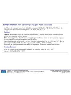
5 Thecenter tube would carry the cryogenic fluid. It is held in place by a spacer madeof materials that are poor conductors of heat. The outer tube holds a vacuum toprotect the inner SteelTubingProton transfer LineVacuumLiquid Nitrogen1-phase Heluim2-phase HeliumSuperinsulationThis is a diagram of the proton transfer line, but all fixed target transfer lines areconstructed similarly. The transfer line consists of five stainless steel tubes thathold vacuum and superinsulation, spacers (not shown), liquid nitrogen, two-phase helium, and single-phase helium. The vacuum, insulation (wrapped at 60layers per inch), and liquid nitrogen all act as a shield for the supply and Primer4 The innermost tube handles the two-phase return from the magnet string.
6 Thenext outer tube supplies the magnet string with liquid helium . You may think itodd that we have a gas and a liquid in contact, by conduction, with each other,but please note that these two tubes do not act as a heat exchanger in the wayyou might think. The returning two-phase gas, flowing through the center tube,is expanded after leaving the magnet string. The affect of this expansion is thatthe two-phase return gas becomes slightly colder than the single-phase supply,thus the two-phase return gas acts as a precooler for the supply VALVESC ryogenic valves are necessary to control the flow of both gas and liquid phasesflowing through the refrigerator. The best valves offer the followingcharacteristics: low heat leak, reliable operation, small heat capacity, smallresistance to flow, simplicity and economy of construction, and adaptability ofinsertion into ordinary vacuum-insulated lines.
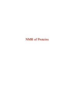
7 The following information onKautzky valves describes one of Fermilab's important KAUTZKY VALVEThe development of Fermilab's cryogenic system required new components, oneof which was a relief valve that could reseal itself after venting. The Kautzkyvalve is a pressure relief valve used on every superconducting magnet. Thevalve vents helium in the event that internal pressure raises too high, as from aquench, and then reseats SeatDirection of System FlowGas SpringGas SpringBoltsBoltsCryogenics Primer5 The most important aspect of the Kautzky valve is its chatter free ability to openand reseal. It's able to do this because the poppet moves counter to the flowwhen opening.
8 During a quench, the seating force is reduced by the highcryostat pressure acting on the inner surface of the actuator, which opposes the"gas spring." When the force holding the poppet on its seat is reduced to zero,the poppet begins to open. The force of this flow pushes the poppet fully as the flow past the poppet equalizes, the poppet remains open down to afew psi less than the pressure that caused it to open. If the pressure continues todrop, the remotely supplied pressure of the "gas spring" will close the EXCHANGER (HEX)Heat transfer occurs when objects, gasses, or fluids of different temperaturesencounter each other. The modes of heat transfer are through conduction,convection, or ExchangerThere are many types of heat exchangers used in cryogenic systems.
9 Thisdiscussion will limit itself to the types of heat exchangers used by the Main Ringand the Research Division in their satellite refrigerators. The construction ofthese heat exchangers is commonly referred to as tube and shell & SHELL HEAT EXCHANGERSThe tube portion is a finned copper tubing, which is wound around a mandrel ina spiral configuration like a spring. The return shell path is an annular spacesurrounding this tube bundle. Heat exchange is accomplished by convectionfrom the fluid over the surface of the copper tubing and by conduction throughthe tubing wall. The entire assembly is enclosed in a vacuum vessel and superinsulated to reduce heat loss to the ambient environmental Primer6 COUNTER FLOWT inS out T out S inT in = S out and T out = S inIn a perfect heat exchanger, the counter flow streams exchange heat with 100%efficiency.
10 The supply side outlet temperature would be equal to the return sideinlet temperature and the supply side inlet temperature would equal the returnside outlet temperature. Unfortunately, there are no perfect heat are always losses due to inefficient insulation, poor vacuum and heattransfer through materials such as though this is not a perfect heat transfer , it is very important to understandthese temperature relationships. So let's follow a cascade of heat exchangers andsee the temperature I300 K300 K 80 K 80 KHelium InNitrogen InHeat exchanger I, in a satellite refrigerator system, uses liquid nitrogen on the"shell" side as the cooling medium. The "tube" side, which contains the hothelium gas, is totally immersed in a bath of liquid nitrogen.