Transcription of REHABILITATING GRAVITY FILTER SYSTEMS USING THE …
1 The Leopold Company, Inc. WHITE PAPER REHABILITATING GRAVITY FILTER SYSTEMS USING THE DUAL PARALLEL lateral Thomas M. Getting, , DEE, Filtration Product Manager John Geibel, , Chief Engineer Andrew Eades, European Sales Manager Company, Inc. 227 South Division Street, Zelienople PA 16063, USA. ABSTRACT A practical approach is presented to REHABILITATING GRAVITY , granular media FILTER SYSTEMS USING the dual parallel lateral underdrain and modern techniques to update the other FILTER components. The first area of investigation is the arrangement and adequacy of the backwash flow to the FILTER box. Many times this arrangement has an inherently poor design that contributes to the mal-distribution of the backwash water flow into the FILTER .
2 Modifications to inadequate designs are discussed which promote uniform cleaning of the granular media bed. The dual parallel lateral underdrain is then applied to the FILTER box and this paper describes the principles and operation of the dual parallel lateral as compared to single pass underdrain SYSTEMS . Several different approaches to introducing air to the dual parallel lateral system are discerned. Gravel support of media is compared to porous, gravelless support plates. Benefits and features of both SYSTEMS are discussed. Design of various filtration media beds are presented along with the standard material tests used in the American Water Works Association B100 Standard for Filtering Material.
3 This presentation concludes with the updating of the FILTER system control scheme. Modern data acquisition and control SYSTEMS are applied to the FILTER for optimum performance of the system . KEYWORDS Dual-Parallel lateral , Granular, Gravelless, Media, Filtration, Rapid GRAVITY FILTER , Rehabilitation, Underdrain INTRODUCTION GRAVITY filtration in water treatment is the passage of water through a porous, granular medium for the physical removal of suspended solids. The earliest written records of water treatment, dating from about 4000 BC, mention filtration of water through charcoal or sand and gravel. Although a number of modifications have been made in the manner of application, filtration remains one of the fundamental process technologies associated with water treatment.
4 The Leopold Company, Inc. WHITE PAPER 2 Granular FILTER media (effective sizes ranging from mm) will generally remove particles This article is the sole property of the F. B. Leopold Co., Inc. and is not to be reproduced or reprinted in whole or in part without the permission of the F. B. Leopold Co., Inc. that are larger than 7-10% of the smallest media grains. Most water treatment applications try to remove color and all solids greater than 10-20 microns. Smaller particles are removed USING chemicals to destabilize colloidal dispersions and enhance the growth or coagulation of particles into a size that can be removed.
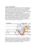
5 In GRAVITY filters, the conditioned raw water is introduced into the top of a basin, flows down through the selected media bed, and is collected by the underdrain system as shown in Figure 1. The driving force through the system is the distance from the water level over the FILTER to the first air break which is usually into a clearwell or control weir. As solids are accumulated in the FILTER media, the headloss or force required to maintain flow increases. A point is reached where either the flow cannot be maintained or solids are driven through the FILTER . An upward flow of water or a combination of air and water (called a backwash) is used to scour and fluidize the media thereby removing the accumulated particles and restoring the driving force.
6 The effectiveness of a backwash operation is measured by the resulting cleanliness of the media and the associated costs of power and water required to perform the backwash. Figure 1. Typical GRAVITY FILTER system The current best practice backwash is to begin with an air scour to agitate the media surface, followed by an air scour with low rate water backwash in the collapse-pulse manner to agitate the whole bed, and finally a high rate water only backwash to expand the media and remove particles from the media bed. Several studies have shown that the air/water backwash regime provides a cleaner media USING less backwash water.
7 Amirthirajah et al. has shown that a backwash in the collapse-pulse region cleans dual media and granular activated carbon the best. Collapse-pulse is defined as the combination or air and water that allows the air to compress and expand as it passes through the bed. Achieving a collapse-pulse condition therefore will give the optimum FILTER wash and should be used in the design of the backwash system . The Leopold Company, Inc. WHITE PAPER 3 SINGLE-PASS UNDERDRAIN SYSTEMS The purpose of the underdrain system in a GRAVITY FILTER during the filtering mode is to support the media, collect the treated water, and channel it to the discharge piping to the clearwell.
8 When the FILTER media becomes dirty, the underdrain is used to evenly distribute the backwash water and air used to flush out the accumulated particles. The backwash mode is where the underdrain is most critical. If the backwash water and air are not evenly distributed, dirt can accumulate within the FILTER media causing uneven forward and backwash flows . Over time as the dirt accumulates in the media, usually in the form of mudballs, the FILTER run-time and particle removal performance deteriorates. Uniform backwash distribution is critical in maintaining the long-term performance of rapid GRAVITY filters. There are two basic types of underdrain SYSTEMS in general use.
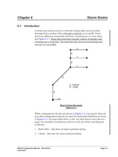
9 The first are the single pass SYSTEMS and the latter are the dual-pass SYSTEMS . Examples of single pass underdrain SYSTEMS are pipe laterals, nozzle/strainers, Wheeler SYSTEMS , Tee Pees or folded plates, etc. shown in Figure 2. The flow distribution of these types of single pass underdrain SYSTEMS is dependent upon a single series of orifices contained within the underdrain. In order to maintain an even distribution of flow, the lateral lengths must be kept to a minimum or in the case of the nozzle/strainers, the plenum must be made deep. A deeper plenum adds significant additional initial construction costs. Pipe Laterals Nozzle Underdrains The Leopold Company, Inc.
10 WHITE PAPER 4 Folded Plate/Tee Pees Wheeler Underdrains Figure 2. Single Pass Underdrains Figure 3 shows the distribution of backwash water in a single pass underdrain system . The flow velocity is the highest at the inlet area and the water tends to pass the first few orifices. As the flow proceeds through the lateral with velocity and quantity decreasing, more flow proceeds through the orifices at the end of the lateral . Because of this inherent characteristic of single pass laterals, the lateral lengths are best kept less than10 feet. Figure 3. Flow distribution in a single pass lateral The Leopold Company, Inc.