Transcription of Reinforced Concrete Design - Texas A&M University
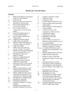
1 ARCH 631 Note Set F2013abn 1 Reinforced Concrete Design Notation:a = depth of the effective compression block in a Concrete beam A = name for area Ag = gross area, equal to the total area ignoring any reinforcement As = area of steel reinforcement in Concrete beam Design = area of steel compression reinforcement in Concrete beam Design Ast = area of steel reinforcement in Concrete column Design Av = area of Concrete shear stirrup reinforcement ACI = American Concrete Institute b = width, often cross-sectional bE = effective width of the flange of a Concrete T beam cross section bf = width of the flange bw = width of the stem (web) of a Concrete T beam cross section cc = shorthand for clear cover C = name for centroid = name for a compression force Cc = compressive force in the compression steel in a doubly Reinforced Concrete beam Cs = compressive force in the Concrete of a doubly Reinforced Concrete beam d = effective depth from the top of a Reinforced Concrete beam to the centroid of the tensile steel d = effective depth from the top of a Reinforced Concrete beam to the centroid of the compression steel db = bar diameter of a reinforcing bar D = shorthand for dead load DL = shorthand for dead load E = modulus of elasticity or Young s modulus = shorthand for earthquake load Ec = modulus of elasticity of Concrete Es = modulus of elasticity of steel f = symbol for stress fc = compressive stress = Concrete Design compressive stress fs = stress in the steel reinforcement for
2 Concrete Design = compressive stress in the compression reinforcement for Concrete beam Design fy = yield stress or strength F = shorthand for fluid load Fy = yield strength G = relative stiffness of columns to beams in a rigid connection, as is h = cross-section depth H = shorthand for lateral pressure load hf = depth of a flange in a T section Itransformed = moment of inertia of a multi-material section transformed to one material k = effective length factor for columns = length of beam in rigid joint = length of column in rigid joint ld = development length for reinforcing steel = development length for hooks ln = clear span from face of support to face of support in Concrete Design L = name for length or span length, as is l = shorthand for live load Lr = shorthand for live roof load LL = shorthand for live load Mn = nominal flexure strength with the steel reinforcement at the yield stress and Concrete at the Concrete Design strength for Reinforced Concrete beam Design Mu = maximum moment from factored loads for LRFD beam Design n = modulus of elasticity transformation coefficient for steel to Concrete = shorthand for neutral axis ( )
3 PH = chemical alkalinity P = name for load or axial force vector sA cf sf b c dhlARCH 631 Note Set F2013abn 2 Po = maximum axial force with no concurrent bending moment in a Reinforced Concrete column Pn = nominal column load capacity in Concrete Design Pu = factored column load calculated from load factors in Concrete Design R = shorthand for rain or ice load Rn = Concrete beam Design ratio = Mu/bd2 s = spacing of stirrups in Reinforced Concrete beams S = shorthand for snow load t = name for thickness T = name for a tension force = shorthand for thermal load U = factored Design value Vc = shear force capacity in Concrete Vs = shear force capacity in steel shear stirrups Vu = shear at a distance of d away from the face of support for Reinforced Concrete beam Design wc = unit weight of Concrete wDL = load per unit length on a beam from dead load wLL = load per unit length on a beam from live load wself wt = name for distributed load from self weight of member wu = load per unit length on a beam from load factors W = shorthand for wind load x = horizontal distance = distance from the top to the neutral axis of a Concrete beam y = vertical distance = coefficient for determining stress block height, a, based on Concrete strength, = elastic beam deflection = strain = resistance factor = resistance factor for compression = density or unit weight = radius of curvature in beam deflection relationships = reinforcement ratio in Concrete beam Design = As/bd = balanced reinforcement ratio in Concrete beam Design = shear strength in Concrete Design Reinforced Concrete Design Structural Design standards for Reinforced Concrete are established by the Building Code and Commentary (ACI 318-11)
4 Published by the American Concrete Institute International, and uses ultimate strength Design . Materials f c = Concrete compressive Design strength at 28 days (units of psi when used in equations) Deformed reinforcing bars come in grades 40, 60 & 75 (for 40 ksi, 60 ksi and 75 ksi yield strengths). Sizes are given as # of 1/8 up to #8 bars. For #9 and larger, the number is a nominal size (while the actual size is larger). 1 cf c balanced c ARCH 631 Note Set F2013abn 3 Reinforced Concrete is a composite material, and the average density is considered to be 150 lb/ft3. It has the properties that it will creep (deformation with long term load) and shrink (a result of hydration) that must be considered. Plane sections of composite materials can still be assumed to be plane (strain is linear), but the stress distribution is not the same in both materials because the modulus of elasticity is different.
5 (f=E ) In order to determine the stress, we can define n as the ratio of the elastic moduli: n is used to transform the width of the second material such that it sees the equivalent element stress. Transformed Section y and I In order to determine stresses in all types of material in the beam, we transform the materials into a single material, and calculate the location of the neutral axis and modulus of inertia for that material. ex: When material 1 above is Concrete and material 2 is steel: to transform steel into Concrete concretesteelEEEEn 12 to find the neutral axis of the equivalent Concrete member we transform the width of the steel by multiplying by n to find the moment of inertia of the equivalent Concrete member, Itransformed, use the new geometry resulting from transforming the width of the steel Concrete stress: dtransformeconcreteIMyf steel stress: dtransformesteelIMynf yE Ef111 yE Ef222 12 EEn ARCH 631 Note Set F2013abn 4 Reinforced Concrete Beam Members Ultimate Strength Design for Beams The ultimate strength Design method is similar to LRFD.
6 There is a nominal strength that is reduced by a factor which must exceed the factored Design stress. For beams, the Concrete only works in compression over a rectangular stress block above the from elastic calculation, and the steel is exposed and reaches the yield stress, Fy For stress analysis in Reinforced Concrete beams the steel is transformed to Concrete any Concrete in tension is assumed to be cracked and to have no strength the steel can be in tension, and is placed in the bottom of a beam that has positive bending moment ARCH 631 Note Set F2013abn 5 02 )xd(nAxbxsThe neutral axis is where there is no stress and no strain. The Concrete above the is in compression. The Concrete below the is considered ineffective. The steel below the is in tension. Because the is defined by the moment areas, we can solve for x knowing that d is the distance from the top of the Concrete section to the centroid of the steel: x can be solved for when the equation is rearranged into the generic format with a, b & c in the binomial equation: 02 cbxax by aacbbx242 T-sections If the is above the bottom of a flange in a T section, x is found as for a rectangular section.
7 If the is below the bottom of a flange in a T section, x is found by including the flange and the stem of the web (bw) in the moment area calculation: Load Combinations - (Alternative values allowed) + + (Lr or S or R) + (Lr or S or R) + ( or ) + + + (Lr or S or R) + + + + + 0)xd(nA2hxbhx2hxhbsfwffff f f bw bw hf hf b As a/2 T T C C x a= 1x c actual stress Whitney stress block d h ARCH 631 Note Set F2013abn 6 Internal Equilibrium C = compression in Concrete = stress x area = f cba T = tension in steel = stress x area = Asfy C = T and Mn = T(d-a/2) where f c = Concrete compression strength a = height of stress block b = width of stress block fy = steel yield strength As = area of steel reinforcement d = effective depth of section (depth to of reinforcement) With C=T, Asfy = f cba so a can be determined with bffAacys Criteria for Beam Design For flexure Design .
8 Mu Mn = for flexure (when the section is tension controlled) so, Mu can be set = Mn = T(d-a/2) = Asfy (d-a/2) Reinforcement Ratio The amount of steel reinforcement is limited. Too much reinforcement, or over- Reinforced will not allow the steel to yield before the Concrete crushes and there is a sudden failure. A beam with the proper amount of steel to allow it to yield at failure is said to be under Reinforced . The reinforcement ratio is just a fraction: bdA s (or p) and must be less than a value determined with a Concrete strain of and tensile strain of (minimum). When the strain in the reinforcement is or greater, the section is tension controlled. (For smaller strains the resistance factor reduces to see tied columns - because the stress is less than the yield stress in the steel.) Previous codes limited the amount to balanced where balanced was determined from the amount of steel that would make the Concrete start to crush at the exact same time that the steel would yield based on strain.
9 ARCH 631 Note Set F2013abn 7 Flexure Design of Reinforcement One method is to wisely estimate a height of the stress block, a, and solve for As, and calculate a new value for a using Mu. 1. guess a (less than ) 2. 850 3. solve for a from Mu = Asfy (d-a/2) : ysufAMda 2 4. repeat from 2. until a found from step 3 matches a used in step 2. Design Chart Method: 1. calculate 2bdMRnn 2. find curve for f c and fy to get 3. calculate As and a andbdAs bffAacys Any method can simplify the size of d using h = Maximum Reinforcement Based on the limiting strain of in the steel, x(or c) = so )d.(a37501 to find As-max ( 1 is shown in the table above) Minimum Reinforcement Minimum reinforcement is provided even if the Concrete can resist the tension. This is a means to control cracking. Minimum required: but not less than: where cf is in psi. This can be translated to but not less than for which is permitted to be (tensile strain of ) from Reinforced Concrete , 7th, Wang, Salmon, Pincheira, Wiley & Sons, 2007 ycff 3min yf200)dwb(yfcfsA 3)dwb(yfsA200 ARCH 631 Note Set F2013abn 8 Compression Reinforcement If a section is doubly Reinforced , it means there is steel in the beam seeing compression.
10 The force in the compression steel at yield is equal to stress x area, Cs = Ac Fy. The total compression that balances the tension is now: T = Cc + Cs. And the moment taken about the centroid of the compression stress is Mn = T(d-a/2)+Cs(a-d ) where As is the area of compression reinforcement, and d is the effective depth to the centroid of the compression reinforcement T-sections (pan joists) T beams have an effective width, bE, that sees compression stress in a wide flange beam or joist in a slab system. For interior T-sections, bE is the smallest of L/4, bw + 16t, or center to center of beams For exterior T-sections, bE is the smallest of bw + L/12, bw + 6t, or bw + (clear distance to next beam) When the web is in tension the minimum reinforcement required is the same as for rectangular sections with the web width (bw) in place of b. When the flange is in tension (negative bending), the minimum reinforcement required is the greater value of or where cf is in psi, bw is the beam width, and bf is the effective flange width Cover for Reinforcement Cover of Concrete over/under the reinforcement must be provided to protect the steel from corrosion.
