Transcription of Relationship of Design Pressure, Test Pressure & …
1 P O B o x 3 11 5 4 S t . L o u i s, M O 6 3 1 3 1 - 0 1 5 4 P h o n e : ( 3 1 4 ) 9 6 6 - 8 9 1 9 ~ E m a i l : w m h u i t t @ a o l . c o m 1 Relationship of Design Pressure , Test Pressure & PSV Set Point By William M. Huitt (From a paper dated June 28, 2004 in response to numerous questions about the topic) There have been a number of issues and questions raised over the topic of pipe system leak test pressures, Design pressures, and how they relate to the Pressure relief device set point Pressure .
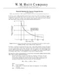
2 The easiest way to clarify their Relationship is to use, as an example, a simplified flow diagram with only the necessary elements included. Using the following simplified flow diagrams this paper will describe the Relationship between the Pressure relief device, its set point and how and when it affects the Design Pressure of a piping system, and therefore its leak test Pressure . The leak test Pressure ( , hydro test or pneumatic test) calculation is , per ASME , based on the Design Pressure of a piping system.
3 A system, from the standpoint of Pressure testing, can be defined in different ways. In context it can refer to: 1. A test circuit, which is an installed segment of a piping system, including all pipe, fittings and components that have been delineated and identified on some document such as a flow diagram. 2. It can also refer to all pipe, fittings, components and equipment in the same service and under the same Pressure and temperature conditions. 3. And lastly, it can refer to a complete operating system with parameters defined by the process or utility description.
4 With regard to this paper, when referring to a system the second definition will apply, as defined above: all pipe, fittings, components and equipment in the same service under the same Pressure and temperature conditions. Piping systems are not required, under B31, to be protected by a Pressure relief device. For piping systems that are not protected by a safety relief device, or for systems that can be isolated from a relieving device, the piping shall be designed to withstand the highest Pressure that can be developed in that section of pipe ( para.)
5 Definitions In explaining their Relationship we have to first of all define Design Pressure , leak test Pressure , and Pressure relief device requirements as well as describe their purpose. Design Pressure : As defined in ASME The most severe condition of coincident internal or external Pressure and temperature (minimum or maximum) expected during service . There are caveats associated with that statement, but since they do not affect this discussion we won t involve them. They can be found in para.
6 What means by the previous statement is that the Owner has the responsibility of determining the most severe condition the pipe system will experience. Those severe conditions, both Pressure and temperature, are what will be used along with fluid service compatibility, as a basis for specifying the material of construction for the piping material. The Design Pressure and temperature are used for all material requirements to ensure integrity of the piping system against the most severe service conditions. Within the ASME BPV Code Section VIII, Division I, the terms Maximum Allowable Working Pressure (MAWP) and Vessel shall be interpreted to mean Design Pressure and Piping System respectively when applied to piping systems.
7 This is in relation to Pressure relieving devices. Leak Test Pressure : There are two basic methods of leak testing piping systems, Hyrdrostatic and Pneumatic. There are other alternative Pressure test methods, but they are not within the scope of this paper. Hydrostatic Leak Test Pressure : Hydrostatic leak test Pressure is based on the following equations: or (A) (B) 2 Use equation A for all services in which the Design temperature of the fluid service does not exceed the test fluid temperature. ASME further states that if the fluid service temperature is in excess of the test fluid, equation (B) shall be used.
8 However, if the stress value of the pipe material at the Design temperature is unchanged from its ambient values through its values at the Design temperature, then equation (A) can still be used. Refer to Table 3 for examples of stress values for commonly used material. As an example, ASTM A106 Gr B seamless carbon steel has a stress value of 20,000 psi throughout the temperature range of ambient through 400 F. Above that temperature the stress values decrease as the temperature increases. Through 400 F, for that material, you can see that ST and S cancel each other leaving the engineer with equation (A).
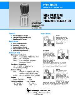
9 Pneumatic Leak Test Pressure : Pneumatic Leak Test Pressure is calculated based on 110% of the Design Pressure . Pressure Relief Device: The relief valve is actuated by inlet static Pressure and designed to open during emergency or abnormal conditions to prevent a rise of internal fluid Pressure in excess of a specified Design value. Pressure relief devices come in various types and styles. The relief valve type can be specified in the following styles: relief valve, safety valve, safety relief valve, conventional Pressure relief valve, balanced Pressure relief valve, and pilot operated Pressure relief valve.
10 There is also the non-reclosing Pressure relief valve. The rupture disc type can be specified as a fragmenting style or non-fragmenting style. There is also the pin-actuated device. For this paper the type or style of Pressure relief device is not relevant, what is relevant is that when one is present in the system how does it relate to the Design Pressure and therefore the test Pressure . The Basics The ASME BPV Code requires that equipment under its Code stamp be protected from over pressurization; there is no such requirement for piping systems.