Transcription of RELIABILITY ISSUES AND FAILURE MECHANISMS …
1 RELIABILITY ISSUES AND FAILURE MECHANISMS - moisture absorption All polymeric materials are permeable to moisture to a lesser or greater extent, and will absorb moisture when installed in a humid environment. moisture absorption will thus have an effect on both packages and on boards in fact any polymeric material used in assembly. The amount of water absorbed, and the rate at which equilibrium is reached will depend on the type of package, the material, and the conditions under which the part is stored. The normal method of evaluating moisture take-up is by measuring the percentage weight gain. For example, for a PBGA exposed at 85 C/85%RH, equilibrium at about weight gain occurs after 1 week (168 hours), but 70% of that absorption takes place in the first day. The popcorn effect'. If plastic packaged parts have been manufactured or stored under humid conditions, they can develop cracks on soldering, by whatever method this is carried out.
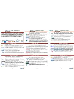
2 Absorbed moisture turns to steam when heat is applied, building up a pressure of several atmospheres in the interior of the component, which causes the housing to balloon' and crack. The stages of this so-called popcorn effect' are shown in Figure 1. Ultrasonic microscope photographs confirm that delamination has occurred, providing an easy path to the chip and bond pads both for moisture and external sources of ionic contamination. C-scan image of PLCC, showing extensive internal delamination due to popcorning Figure 1: moisture -induced crack generation and delamination model The sensitivity to moisture will depend on the construction: at the device level, delamination effects can be reduced by perforating lead-frames to improve adhesion, decreasing the particle size of fillers, and stamping lead-frames to eliminate burr formation sites that contribute to stress concentration.
3 The popcorn problem is most commonly seen with large flat devices, and has been a particular problem with Ball Grid Arrays. The effect can, however, be largely eliminated by ensuring that the components are manufactured and stored in a strictly dry environment, and only exposed to factory conditions for a very short period prior to solder assembly. J-STD-020, a joint EIA/IPC standard, defined six (now 8) levels of susceptibility to moisture in terms of the maximum allowable assembly floor life. The levels given in Table 3 are related to specific test conditions that are applied before reflow soldering and evaluation. Table 3: Floor life for components of different moisture sensitivity levels (J-STD- 020B). Devices which pass the Level 1 test are classified as not moisture sensitive, and do not require dry packaging.
4 All other parts should be fully dried by baking by the manufacturer and vacuum sealed in a moisture resistant bag, together with a packet of desiccant and a moisture indicator card. JEDEC specification JEP113B. Symbol and Labels for moisture -Sensitive Devices recommends a standard ID label, which incorporates the moisture -sensitive three raindrops' symbol. After opening the bag, the moisture indicator card should always be checked to ensure the seal was not impaired. The parts then should be mounted within the floor life time given by the sensitivity level hours, depending on ambient conditions, or stored in an environment which prevents the total absorbed moisture from exceeding of the total package weight. A second caution' label on the bag should state the sensitivity level and the recommended heat treatment to be used to dry out packages suspected of having been stored in humid conditions.
5 Typical conditions for re-baking are 192 hours at 40 45 C and <5%RH, or 24 hours at 120 130 C, the choice depending on the rated maximum temperature of the local packaging: reeled parts, for example, may not be able to withstand the higher temperature without the tape deteriorating. Parts which will only pass Level 6 are regarded as extremely moisture -sensitive, with the dry pack providing inadequate protection. In such cases the customer must be advised of the classification at shipment, and a special warning label included to indicate that parts must be baked dry within the six hours preceding reflow. The minimum bake time and temperature for the device need to be determined from absorption studies. moisture and boards The effects of moisture are not limited to the popcorning of active components;. equivalent effects may be found with PCBs exposed to moisture and then soldered.
6 Where damp boards are not thoroughly dried beforehand, they may delaminate during soldering, or at the very least there will be problems, such as solder balling on reflow and spitting and solder voids on wave soldering. As with popcorning, most of the moisture -related ISSUES are exposed during assembly. However, moisture can have an ongoing impact on circuit performance by affecting the electrical characteristics of the laminate. The higher the ambient relative humidity, the greater the moisture on the surface as well as in the bulk of the material. Ulbricht reported that the surface resistance expressed in ohms/square can vary as much as 4 5 orders of magnitude over a 30-90% relative humidity range. Dielectric losses also increase with increasing moisture content. From this, one might suppose it better to keep parts dry, and assemble in a dry atmosphere.
7 However, at humidities below 30%, static charging problems become severe. As a compromise, most fabrication and assembly shops operate at a relative humidity of around 50%. moisture resistance of PEMs We have seen already that moisture has an impact on plastic-encapsulated micro- circuits (PEMs) in the short term, before use, where absorbed moisture can result in FAILURE . There is also a concern that moisture , in conjunction with sources of ions within the PEM, might result in unreliability. It was this concern that led to delays in the 1980s in converting from hermetic packages to PEMs for applications such as telephone exchange equipment. Whilst hermetic packages can be assessed directly by leak testing, parts embedded in polymer have to be tested indirectly for moisture resistance by looking for the adverse effects of moisture penetration.
8 This is done by subjecting parts simultaneously to high temperature and high humidity for an extended period, typically 1,000 hours, and is a destructive sample test to qualify the batch, rather than a 100% screen. Standard conditions start at 85 C/85% relative humidity (RH), but more severe tests are frequently specified, in order to test the limits of the latest encapsulating processes. Device FAILURE will generally be accelerated by voltage as well as by temperature and humidity, and tests with applied bias are sometimes specified. However, heat generated by the chip itself will reduce moisture concentration at the surface and thus has some protective effect. Special test chambers, often referred to as autoclaves because of their origin in medical sterilisation applications, apply elevated temperature and 100% RH.
9 Simultaneously, but care has to be taken to ensure that moisture does not condense on the parts under test, especially when bias is applied to devices. In hermetic packages, moisture can be excluded almost completely, but it can only be minimised in plastic packages. Not only are the intermolecular spaces of the plastic large enough to allow the diffusion of water, but additional paths for moisture penetration are found at the interfaces of different materials with badly optimised or weakened mutual adhesion. The most important interfaces are: moulding compound to lead-frame moulding compound to semiconductor die moulding compound to bond wires polymer to filler within the moulding compound. Stress is built up during shrinkage after moulding and by CTE mismatch between the different package materials. Unless precautions are taken, this stress will lead to adhesion FAILURE and delamination, enhancing the diffusion rate of moisture at the interfaces.
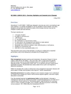
10 Stress can also damage the chip surface and create micro-cracks in the package, all of which facilitate the penetration of moisture , as shown schematically in. Figure 2. Figure 2: moisture penetration and structure of package Important factors in minimising interface problems are: The design of the lead-frame, both to increase the path length for incoming moisture and to enhance the strength of the assembly. Strategies include mechanical locking with lead fishtails' and die pad perforations, and improving the overall package symmetry by using depressed pads. The compatibility, CTE mismatch, thermal resistance and adhesion of the materials used for lead-frame and encapsulation. The lead-frame cleaning and plating processes used after moulding. Reducing stresses in the lead-frame trim and form operation. Author: Martin Tarr Source.