Transcription of Reliability of CDE Aluminum Electrolytic Capacitors
1 Reliability of CDE Aluminum Electrolytic Capacitors Sam G. Parler, Jr., Cornell Dubilier 140 Technology Place Liberty, SC 29657. Abstract All design engineers who consider using Aluminum Electrolytic Capacitors want to know how long they will last and how many they can expect to fail. Many engineers do not realize that these are actually two different but related questions. In this paper we define life and Reliability in a manner that will hopefully make the distinction clear, and we compare, contrast, and combine life and Reliability models in a way that will allow design engineers to predict from their application conditions not only how long before the Capacitors begin to wear out, but also what the ex- pected failure rate is during the useful life of the Capacitors .
2 Review of wearout life Here, Lb is the base life at an elevated core tem- perature Tm. See Table 1 below. Mv is a voltage Lifetime of Aluminum Electrolytic Capacitors is multiplier, usually equal to unity at the full rated generally specified as the time under certain con- DC voltage, and greater than one at lower DC volt- ditions of applied DC voltage, ripple current, and ambient conditions (temperature, airflow, heatsinking) at which the capacitor's electrical parameters have drifted out of some specified lim- its. The ESR is the first to go, and perhaps it has drifted so high that soon the capacitor will either run so hot that it suddenly shorts out or that it rup- tures its safety vent and begins to dry out and drift open circuit. This lifetime is also known as Wearout Life, Expected Life, Operating Life (Lop), or Use- ful Life.
3 The wearout process is rarely driven by evaporation and escape of the electrolyte unless the safety vent is compromised due to high leak- age current and pressure buildup. True dryout has an effect similar to wearout but usually occurs in Capacitors smaller than 20 cm3 or in Capacitors of older design with poor seal technology. Our published wearout lifetime model follows from the results of life tests. The effect of tem- perature may also be derived from the Arrhenius equation. This derivation and a comparison of volt- age derating equations are presented in our paper Deriving Life Multipliers for Aluminum Electro- lytic Capacitors . The life model is Table 1: CDE Lb and Tm values used in life and L = Lb Mv 2((Tm-Tc)/10) (1). Reliability models 1.
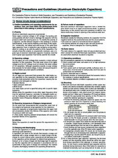
4 Ages. Cornell Dubilier generally uses ure (ESR more than twice the initial limit), and no more than 10% due to open or short circuit. Mv = - (2) The CDE model for wearout lifetime assumes that the lifetime is limited by wearout mechanisms where Va is the applied DC voltage and Vr is the (parametric drift), not by random failures which rated DC voltage. The rated DC voltage is defined might suddenly occur during the life of the capaci- such that the peak applied voltage should not ex- tor. Wearout tends to occur on a group of capaci- ceed this value. tors as an ensemble process, not uniformly distrib- One complication arises because the electrolyte uted over the capacitor life. See Figure 1. The time resistance Ro is a function of the actual core tem- to wearout of a capacitor bank is fairly insensitive perature Tc, the core temperature is a function of to the number of Capacitors in the bank.
5 The power loss, and the power loss is a function of We have found that the wearout lifetime distri- Ro. We use an iterative loop in a Java applet to bution typically has a bell shape, and we model model the core temperature and the life since the this as a normal distribution with a mean of ESR varies with temperature and ripple current. and a standard deviation of We are striving This leads to the question, What do we mean by to be able to state that the mean is greater than the end of life, anyway? How many Capacitors with 90% confidence. Stated another way, our are allowed to fail, and what constitutes a failure? goal is to say with 90% confidence that no more For example, one manufacturer might make a na- than 10% of the Capacitors will have failed from ive and untenable statement such as None of our wearout before t=L.
6 Due to the expected distribu- Capacitors will fail before their rated life expires. tion, this would be about the same as saying with Other capacitor manufacturers might state that no 90% confidence that no more than 1% will have more than 10% of their Capacitors will have failed failed from wearout before t= by the end of their rated life. Still others might add a confidence interval on a similar claim. Improvements in capacitor lifetime It is important that the method of performing the life test and of specifying the allowable degrada- If one looks at the history of lifetime ratings of tion be comparable among capacitor manufactur- large Aluminum Electrolytic Capacitors , one would ers. We use EIA standard IS-749 which specifies find that these have progressed from 1,000 hours capacitor mounting, maximum airflow, inter-ca- at 65 C 40 years ago to up to 15,000 hours at 105.
7 Pacitor spacing, end-of-life definitions. It also C today. This is a factor of 240 in the life, while specifies the lifetime as that time at which 10% of providing more capacitance and higher ripple cur- the Capacitors have failed due to parametric fail- rent handling in the same package. Several factors Probability De nsity and Cumulativ e Distribution Functions for We arout Life A Possible Distribution for Rate d We arout Life L = 100kh 1 Distribution Function Probability Density Function (PDF). Cumulation (CDF). 0 +00. 0 20000 40000 60000 80000 100000 120000 140000 160000 180000. Tim e (hours). CDF(norm) PDF(norm). Figure 1: Probability density and cumulative distribution functions for wearout lifetime 2. have contributed to this accomplishment.
8 These in- allel. Due to adverse effects of fuses (resistance, clude improvements in purity and stability of all cost, size, inductance), it is usually only practical of the capacitor materials and components, espe- to do this in a manner that unfortunately creates cially the electrolyte. Also improved seal technol- the situation that when one capacitor fails short- ogy must receive some credit. circuit, the bank and system cease to function. It is Hence the life model that has been presented is the case, therefore, that the failure rate of the bank expressed independently of and is unaffected by is approximately equal to the number of capaci- the capacitance and the voltage rating, and is rela- tors in the bank multiplied by the failure rate of tively insensitive to the number of Capacitors in a each capacitor.
9 Capacitor bank. It is generally true that smaller Capacitors (CV. rating) are more reliable than larger Capacitors . But Distinguishing lifetime from Reliability when a large CV is needed, the highest Reliability is usually achieved by using a smaller number of Capacitor lifetime is limited by electrochemical physically larger Capacitors . This is true for two degradation that proceeds in a fairly predictable reasons. First, the lower number of terminals, fashion, accelerated by temperature and voltage welds, connections, potential failure sites of the stress. Along the way, however, random failures fewer, large Capacitors is an inherent Reliability are bound to occur if the population is large enough. advantage. Second, large Capacitors are generally These are generally unrelated to wearout, and are designed, constructed, and screened differently instead linked to some latent weakness, usually in from small Capacitors to withstand the application the paper, foil, or connections.
10 These failures are of a large amount of energy connected with most often short-circuits, and they may occur sud- miniscule impedance, which is the situation of a denly and without warning, although occasionally capacitor bank. That said, the capacitor design en- Capacitors may begin to draw excessive leakage gineer can tailor the design of a large or small ca- current and generate sufficient hydrogen gas pres- pacitor to the application of his capacitor in a large sure to rupture the safety vent then subsequently capacitor bank. But the larger capacitor has an in- dry out and fail open circuit. herent advantage in this regard. During the manufacture of the capacitor, rated Wearout lifetime ratings for large and small ca- voltage and temperature are applied in the aging pacitors are about the same.