Transcription of Reliability of Lead-Free Printed Circuit Boards
1 Tarzwell 8/2/05 11:31 AM Page 23. Reliability of Lead-Free Printed Circuit Boards by ROBERT TARZWELL AND KEN BAHL. The assembly process for existing tin/lead sol- der was almost at the limit of the PCB tech- nology's ability to withstand the assembly temperature and time without experiencing via Reliability problems. Most aspects of the PCB such as the traces, solder mask, white marking, laminate and plating are relatively reliable. They rarely fail in use. However, the copper barrel in the vias and holes are the pri- mary failure mode regarding long-term oper- ational failures.
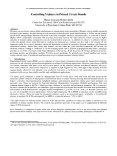
2 We know from years of trial and error that any small change in the process or design of the board might result in danger- ous opens and board failures in the field. Small changes includes items such as: The more assembly cycles that a Circuit experiences, the less reliable the product will be in the field. The hotter or longer the assembly cycles are, the less reliable the product will be. The thicker the laminates, the less reliable, by a considerable factor. Figure 1. Life cycles, assembly cycles, delta swings. The lower the T/g, the less reliable the board .
3 The copper ductility of the plating bath, I have suspected for years that the normal that so many controversial papers and dis- greatly affects the Reliability . PCB was very close to falling off the Reliability cussions were based on whether something The copper plating thickness, if too thin, edge, simply due to the large number of as trivial as leaving or removing the inner- will drastically lower Reliability . seemingly unrelated factors which would layer pads would affect the board and its ulti- The cure and selection of the prepreg cause terminal failure of the vias by copper mate Reliability related to its fragility.
4 The in multilayers plays a big role in future cracking. The existing copper plated via was industry was spending a great amount of life cycles. anything but bullet proof. The wide range time and effort engineering around many Drilling quality affects hole-plating quality and sensitivity of the copper via cracking factors that are so small and minor that they and therefore reduces the life in the field. problem suggested the vias were close to should not cause any effect. However, they The controversy: to remove or leave the breaking and all they needed was a small can create Reliability issues, either singly or in unused pads in a multilayer, may affect push.
5 I proved the theory correct by finding, combination, when we use our existing plat- Reliability . and eventually fixing, the underlining stress ing methods. The de-smear process is critical to reduced problem which caused the via cracking. The With the new high Reliability via plating via cracking. new high Reliability technology ensured that technology, the vias are so strong that they Any small pinhole in the copper wall is the manufactured vias were so strong that are unaffected by most factors. The T/g of concern for Reliability . most of the previous problems no longer the material is no longer a concern as the The expansion rate of the z-axis is critical.
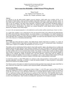
6 Affected long-term Reliability . The large vias do not crack with repeated thermal A high number of thermal cycles over number of small factors which previously cycles. Reliability does not now relate to the 100 C delta caused reduced operational compromised the via Reliability were T/g value, the new copper plating is so strong life. reduced to almost no effect. The simple fact that the drilling quality does not directly THE board AUTHORITY . 2 0 0 5 23. tarzwell 8/2/05 11:31 AM Page 24. Figure 2. Picture of the extreme angle the pads can endure with the expansion force of the laminate.
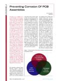
7 Cause cracking. The new plating process pro- vides a hole wall that is stronger than the z- Figure 3. Differential expansion rates between laminate and copper. axis expansion forces, e- modules (Young's modules) of any laminate. The copper duc- tility is also no longer a controlling factor of long-term Reliability . Simply put, the new higher Reliability via is so robust that I have yet to crack one in many hundreds of ther- mal tests, solder shock tests, long thermal cycles at very high temperatures or very low temperatures. The new via looks and oper- ates the same as a regular via, only vastly stronger.
8 Looking at both normal and new technologies you would not be able to see the difference. The effect of the new Lead-Free assembly solder cycles and higher temperatures will be at a reduced Reliability due to early via cracking in the hole. Tests have shown the old FR-4 laminate 175 T/g is not suitable for Lead-Free applications. This mandates the use of new laminate with the required testing and proving period before we are really sure of its Reliability . Additionally, testing has confirmed early copper via cracking with the hotter, longer, Lead-Free solder assembly cycle.
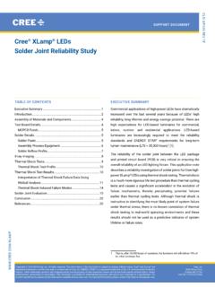
9 The Figure 4. Normal Tg 175 HATS testing results of only 250 to 450 cycles. extra Lead-Free temperature causes damage to the copper barrel and subsequently, a lower number of thermal operation cycling will be life survival time to length and temperature ing, causes the copper to start to separate. experienced before copper via cracking. We of the assembly cycle. The hotter or longer After three solder cycles, you may not be are experiencing a 10-20 percent lower ther- the soldering time, the more it stresses the able to see the micro cracks with cross sec- mal operational cycle life per Lead-Free copper vias.
10 Any stress put on the copper via tions. Only by measuring the resistance of a assembly cycle in laboratory testing com- during soldering creates small cracks and fis- string of vias, such as the measurements pared to only five percent with old tin/lead sures within the barrel, at interconnects and used by IST and IRTS HATS testers, will you assembly cycles. along the pad/hole interface. The expansion see a small increase in the resistance as the With five assembly/repair, Lead-Free cycles, forces (Young's modules) of the laminate copper stretches and cracks.