Transcription of REMOTE RELEASE SHACKLE - dcpuk.com
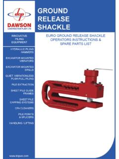
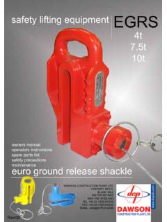
1 RELEASE SHACKLEOPERATORS INSTRUCTIONS & SPARE PARTS LIST100tHYDRAULIC piling HAMMERSEXCAVATOR MOUNTED VIBRATORSEXCAVATOR MOUNTED DRILLSQUIET, VIBRATIONLESSPUSH-PULL PILINGPILE EXTRACTIONSHEET PILE GUIDE FRAMESSHEET PILE CAPPING SYSTEMSCFA CLEANERSPILE POINTS& SPLICERSHANDLING / LIFTINGCONTACTSD awson Construction Plant Hall,Milton Keynes,MK6 1 NEEnglandTel: +44 (0) 1908 240300 Fax: +44 (0) 1908 21 FRONT COVER2 CONTACTS3 CONTENTS4 INTRODUCTION5-6 METHOD OF OPERATION7 ADDITIONAL OPERATION NOTES8-12 INSTALLATION DIAGRAM13-14 SAFETY CHECK LIST15 MAINTENANCE16-17 MAINTENANCE PROCEDURES18 TRAINING19 TROUBLE SHOOTING20-21 WEIGHTS & DIMENSIONS22-23 PARTS LIST24 HOSE KIT25 HYDRAULIC SCHEMATIC26 HAND PUMP RELIEF VALVE ADJUSTMENT27 REAR COVER DETAILSCONTENTSU nder Separate cover: Individual Test Certificate Declaration of 3 INTRODUCTIONThe Dawson 100 tonne RELEASE SHACKLE has been specifically designed for use on large tubes, and when used as a pair, tubes weighing up to 200 tonnes can be pin size is 130mm Diameter and is retracted and engaged hydraulically with a hand pump mounted on the ground complete with spooler to keep the hose under hose length is 60m allowing long piles to be positioned.
2 Because the pin is released hydraulically the operator does not need to be directly underneath the SHACKLE and spooler are mounted into a fabricated frame so that loading and unloading or moving around the job site is just a single crane strength cast steel and hydraulic ram are easily removed for easy body tested to 5 times SWL (safe working load)Each SHACKLE is proof tested to 2 times SWLH ydraulic pin 4shackle in standlifting pointsMETHOD OF OPERATIONWhen lifting tubes a pair of shackles must be used with a spreader beam to keep the two shackles separate when sure the pin is the SHACKLE onto the ground so that it is horizontal, clip in the auxiliary chain that was supplied with the SHACKLE , this will keep the unit horizontal when lifted up to engage with the pin.(See installation diagrams)Position the unit onto the tube and align the pin with the lifting hole in the tube. (Make sure that the hole is positioned the correct distance from the top of the tube)Engage the pin, DOUBLE CHECK THE PIN IS FULLY the auxiliary for the second lift, gently take up the the hose spooler so that it can rotate freely as the pile is winder handle and place in the pile up to vertical and position; take care not to snag the hydraulic control the pile is safely positioned the SHACKLE can be 5 METHOD OF OPERATION (con t)To RELEASE the SHACKLE :MAKE SURE THERE S NO LOAD ON THE SHACKLEOn the spooler and hand pump unit switch the selector to RELEASE pin Pump with the extension bar until the pin is fully back.
3 Visually check that the indicator is both shackles are released lift them clear of the pile, the spreader beam should stop the two shackles from swinging together and the shackles to the ground, winding the control hose onto the spooler as they are the shackles safely in the stand until needed 6 ADDITIONAL OPERATION NOTESpg 7 AUXILIARY HANDLING CHAINSWhen offering the SHACKLE up to the horizontal pile or tube the SHACKLE must be in the horizontal position. To achieve this a set of auxiliary handing chains must be used, they hook on to the M16 eye bolts on the SHACKLE , they are shown pictorially on page length of these handing chains is critical, but depends on the bow SHACKLE and spreader beam setup. For this reason the auxiliary handling chains are not adjusted for length and are purposely left long. Included in the kit are two Gunnebo BKG-6-10 RT hooks and two Gunnebo G-6-10 couplers per SHACKLE . Once the spreader beam, bow SHACKLE , Dawson 100 ton RELEASE SHACKLE and spreader beam set-up has been determined then the length of the auxiliary chains can be one end to the auxiliary point on the spreader beam and the other end to the eye bolts on the SHACKLE , do some trial lifts and adjust the length of chain until the SHACKLE hangs horizontally, the angle between the SHACKLE and the chain should be more than 45 SHACKLEIf a 120 ton bow SHACKLE is to be used to connect the Dawson RELEASE SHACKLE to the crane then it has to be a specific item, a Gunnebo Super SHACKLE 858 WLL.
4 120t, on this particular bow SHACKLE diameter of the pin bosses is smaller than the usual 120t bow SHACKLE , this allows the lift aperture on the Dawson SHACKLE to be smaller, which adds strength and DIAGRAMpg 8lower shackleto ground1attach auxiliary lifting chains for horizontal lift2use a spreader beam to keep shackles from clashingtube with lifting holes ( 135) at 275mm120t lifting shackles(Gunnebo Super SHACKLE 858)120t lifting shacklesINSTALLATION DIAGRAMpg 9lift shackles and offer upto pile, align pin with holes in tube and engage pin3indicator bar is indouble check pin is fully engagedRaise safety latch & switch selector to engageINSTALLATION DIAGRAMpg 10remove auxiliary horizontal lifting chains from shackle4lift to vertical5unlock hose spooler before lift & replace winder handle back in holderINSTALLATION DIAGRAMpg 11lift to position and secure6 INSTALLATION DIAGRAMpg 12release pin and lift shackles away from tube, return to is retractedindicator bar is outRaise safety latch & switch selector to pin releaseSAFETY CHECK LIST1 Before using the SHACKLE please check the following,a.
5 Establish the weight of the lift and make sure the SHACKLE is working within its Ensure the lifting hole is the correct size and the correct distance from the top of the pile. Note: INCORRECT HOLE POSITION COULD CAUSE SHACKLE 13c. The Safe Working Load rating the SHACKLE is based on a purely tensile (axial) load. When lifting steelwork from the horizontal to vertical or reverse the SHACKLE is de-rated by 50%.d. The Safe Working Load rating of any SHACKLE is based on a purely tensile (axial) load. When lifting steelwork from the horizontal to vertical or the reverse, remember that the SHACKLE becomes de-rated by 50% . a 100 tonne SWL SHACKLE should only be loaded to 50 tonne at the start of a horizontal lift where typically the ground takes the other 50 Ensure that the pin is fully engaged before attempting a lift275MM THROAT DEPTH 135 SAFETY CHECK LIST (con t)pg 14 KEEP FINGERS OUT OF THE SHACKLE THROAT AT ALL TIMES AND WEAR GLOVESDO NOT USE IN TEMPERATURES BELOW -15 C (5 F), CONTACT THE MANUFACTURER FOR FURTHER INFORMATION ON LOW TEMPERATURE NO CIRCUMSTANCES MUST A VIBRO BE USED ON ADJACENT PILES WHEN THE PILE BEING LIFTED IS DEPENDENT UPON THE RELEASE SHACKLES FOR SUPPORT.
6 IF DURING USE THE SHACKLE IS SUBJECTED TO ANY IMPACT, CRASHING INTO A PILE OR EACH OTHER, THEN THE SHACKLE MUST BE IMMEDIATELY INSPECTED FOR DAMAGE, THE RAM HOUSING AND ITS SECURING BOLTS, THE HOSES, HOSE FITTINGS AND S IN PARTICULAR. IF ANY DAMAGE IS FOUND DO NOT USE UNTIL IT S Do not modify the lifting shackles or any part of the apparatus. Keep the burning torch well clear4 Care should be taken to avoid the hydraulic control hoses from being When using a pair of shackles make sure a spreader beam is used. If lifting a tube there must be two holes, one each side through the Ensure that all appropriate laws, bye-laws and regulations are complied It is the responsibility of the user to make sure that the load being lifted is capable of resisting the SHACKLE tearing out, a very long thin walled tube at max weight , unlikely but possible ! MAINTENANCEThe SHACKLE is manufactured from high quality material and assembled in such a manner as to offer long service with the minimum of order to keep the SHACKLE in this condition it is necessary to ensure that it is not miss-used and receives regular inspections and SHACKLE body should be checked regularly for any distortion or damage, if you ve bent it - bin it.
7 The pin should be checked for smooth travel and kept lightly oiled on moving the condition of the hydraulic hoses; look for, cuts and the oil level in the reservoir; if it s low top up with oil to 15381712114109133718151614519 MAINTENANCE PROCEDURESpg 16 CHANGING THE MAIN the M8 x 35 cap head screw from the end of the hydraulic cylinder rod. (17)Remove the ring of 15 M8 x 40 bolts from the ram housing. (18)Remove the M6 cap head bolt from the indicator bar. (19)Pull the housing clear. (7)Remove the main pin. (9)Reassemble in reverse order. CHANGING THE HYDRAULIC the M8 x 35 cap head screw from the end of the hydraulic cylinder rod. (17)Check that the system is not under pressure, then remove the M6 x 20 (6) cap head screws from the ram mounting flange. (5)Push out the ram from the rod end; make sure not to lose the 2 small O-rings. (14)Reassemble in reserves 17 PURGING AIR FROM THE HYDRAULIC CIRCUITIf the hydraulic circuit has been disconnected for any reason then air could enter into the purge the system of air,Connect the SHACKLE to the hoses with the QRCs, Take out the two blanked off ports on the SHACKLE and fit a short length of hose between sure the oil tank is filled to the lever for 350 cycles, watch the oil level doesn t PROCEDURESTRAININGB efore allowing operators to use the Dawson hydraulic RELEASE SHACKLE it is important to ensure that they have received basic training in lifting and control of heavy Basic safety in lifting Supervision during lifting Detailed instruction on how the hydraulic RELEASE SHACKLE Safety features of the Hydraulic RELEASE shackle5 Dangers and malpractices6 Correct choice of SHACKLE for the 18 TROUBLE SHOOTINGTHE PIN WILL NOT RELEASE1 Make sure there is no load on the SHACKLE .
8 The pin cannot overcome the weight of the pile hanging on Is there enough RELEASE pressure to pull out the pin, 200 bar is required; fit a gauge onto the test point on the Has the twin hydraulic hose from the spooler to the SHACKLE been Does the hydraulic pump have the correct level of oilTHE PIN WILL NOT ENGAGE1 Make sure there are no obstructions, is the lifting hole in the tube or pile 135?2 Is there enough pressure to push out the pin, at least 50 bar is required; fit a gauge onto the test point on the Check condition of hoses, are there any snags?4 Does the hydraulic pump have the correct level of oilpg 19pg 20 DIMENSIONSWEIGHTSHACKLE = 410 Kgpg 21 DIMENSIONSWEIGHTSHACKLE IN STAND = 645Kg10003801000356520300 FORK LIFT POINTSSTAND LIFT POINTS x4950612 422514183161579131983104111217pg 22 PARTS LIST2pg 23 PARTS LISTITEM BOW SHACKLE -34M16 EYE BOLT-48M6x16 SOCKET HEAD CAP SCREW0M06-016-0257M6x20 SOCKET HEAD CAP SCREW0M06-020-0271 RAM MOUNT FABRICATION600281100 TON SHACKLE BODY600391 PIN6004101 RAM ADAPTOR6005111 RAM CONNECTOR CAP6006121 RAM CONNECTOR SPACER6007131 INDICATOR BAR6008141 RAM6100151 CHECK VALVE6107163 KOENIG PLUGMB-850-070171M8x35 SOCKET HEAD CAP SCREW0M08-35-021816M8x40 SOCKET HEAD CAP SCREW0M08-40-02191M6x100 SOCKET HEAD CAP SCREW0M06-100-02 DESCRIPTIONPART SHACKLE ASSEMBLY6000 STAND6200 HOSE REEL & HAND PUMP6300pg 24 HOSE KIT0102030405 ITEM THERMOPLASTIC HOSE 1/4 x 200MM (1/4/R7HA/200MM/2X20511/04/04)21 SINGLE THERMOPLASTIC HOSE 1/4 x 560MM (1/4/R7HA/560MM/2X20511/04/04)
9 31 SINGLE THERMOPLASTIC HOSE 1/4 x 370MM (1/4/R7HA/370MM/2X20511/04/04)424283 - HOSE KIT52 TWIN THERMOPLASTIC HOSE x 65M (1/4R7HA/T04/65000/4X20511/04/04)62 QRC M/F QUICK RELEASE COUPLING06 GAUGE ON TEST PORTHYDRAULIC SCHEMATICpg 25 RAMHOSE REELINTEGRATED PUMP AND SELECTOR VALVECHECK VALVECHECK VALVESELECTOR VALVEAB102 RELIEF B RELIEF A HAND PUMPTANKHAND PUMP RELIEF VALVE ADJUSTMENTADJUSTABLE RELIEF VALVE, PORT A(RETRACT PIN)200 PSIADJUSTABLE RELIEF VALVE, PORT B(ENGAGE PIN)100 PSIFIRST:UNSCREW THE PLUGSECOND:TIGHTENING THE SCREW, THE VALVE WILL BE CALIBRATED TO A HIGHER PRESSURE VALUE. LOOSENING THE SCREW, THE VALVE WILL BE CALIBRATED TO A LOWER PRESSURE TO BY PASSADJUSTING SCREW TO BYPASSTHIRD:WHEN SET TO THE CORRECT LEVEL, SCREW THE PLUG AGAINpg RESERVES THE RIGHT TO DISCONTINUE equipment AT ANY TIME, OR CHANGE SPECIFICATIONS OR DESIGNS WITHOUT NOTICE OR INCURRING OBLIGATIONSD awson Construction Plant LtdChesney Hall,Milton Keynes,MK6 1NE, EnglandTel: +44 (0) 1908 240300 Fax: +44 (0) 1908 lifting gear