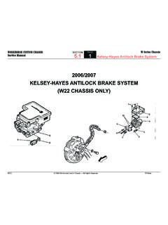
Transcription of Removal and Installation of the DD13,DD15, DD16 Cylinder …
1 1 12 10-14 SUBJECTDATEC ylinder HeadDecember 2014 Additions, Revisions, or UpdatesPublication Number / TitlePlatformSection TitleChangeDDC-SVC-MAN-0081DD PlatformRemoval of the DD13 Cylinder HeadAdded step 26 with step to remove the EGR crossover optional equipment step PN for fuel line service note to step 27 regarding EPA07 note to step 30 regarding possible damage to fuel of the DD13 Cylinder HeadRemoved step to install the EGR crossover step 32 from "remove" to "install".Added a note for head bolt notice regarding proper cleaning note to steps 2 and 4 regarding possible damage to fuelinjector step tool note to step note to step 12 regarding EPA07 steps 24 and PlatformEuroIVRemoval of the DD15and DD16 Cylinder HeadAdded step 24 with step 19 for removing the EGR crossover optional equipment note regarding immersion of new Cylinder head in note to step 24 regarding EPA07 of the DD15and DD16 Cylinder HeadRemoved step 19 for installing the EGR crossover a note for head bolt notice regarding proper cleaning note to steps 2 and 4 regarding possible damage to fuelinjector step
2 Note to step 28 regarding EPA07 engines12 10-14 All information subject to change without notice. 312 10-14 Copyright 2015 DETROIT DIESEL CORPORATION1 12 10-144 All information subject to change without 2015 DETROIT DIESEL CORPORATION 12 10-142 Removal of the DD13 Cylinder HeadWARNING: PERSONAL INJURYTo avoid injury, never remove any engine component while the engine is as off the engine, apply the parking brake, chock the wheels, and perform any other applicable safety the batteries. Refer to OEM the needed, remove the bumper. Refer to OEM the DD13 with short Bumper-to-Back-of-Cab (BBC), remove the hood. Refer to OEM needed, remove the rain tray.
3 Refer to OEM needed, remove the windshield wiper linkage. Refer to OEM the coolant. Refer to section "Cooling System Drain Procedure". and remove the Charge Air Cooler (CAC) ducting from the turbo compressor housing to the CAC. Removethe compressor outlet elbow and inlet the Charge Air Cooler (CAC) hose clamp at the intake throttle adaptor inlet and remove the the coolant level the coolant surge tank. Refer to OEM the DD13 with short Bumper-to-Back-of-Cab (BBC), remove the radiator assembly. Refer to OEM the DD13 with short Bumper-to-Back-of-Cab (BBC), remove the fan assembly. Refer to OEM the camshaft housing. Refer to section " Removal of the Camshaft Housing".
4 Coolant lines (1) from the Exhaust Gas Recirculation (EGR) cooler water manifold assembly to the fuel doserinjector 10-14 All information subject to change without notice. 512 10-14 Copyright 2015 DETROIT DIESEL the EGR vent (de-aeration) line from the EGR cooler water manifold the coolant line from the EGR valve actuator to the EGR cooler water manifold the turbocharger heat the hot pipe from the EGR cooler and EGR valve and discard the spherical clamps. Refer to section "Removalof the Exhaust Gas Recirculation Hot Pipe". the EGR valve actuator to the actuator pull rod from the EGR valve actuator. Refer to section " Removal ofthe Exhaust Gas Recirculation Valve Actuator Pull Rod".
5 The turbocharger flange the Coolant Crossover Pipe. Refer to section " Removal of the Coolant Crossover Pipe". the Intake Throttle Valve (ITV) electrical harness the two bolts attaching the cold boost pipe to the cold boost pipe support : The high pressure fuel rail feed lines, vibration dampers, mounting bracket and hardware are one-time-use components and MUST be replaced any time they are needle, amplifier, and pressure limiting valve (PLV) return to section " Removal of the Needle, Amplifier, and Pressure Limiting Valve Return Lines - Three-Filter System"Refer to section " Removal of the Needle, Amplifier, and Pressure Limiting Valve (PLV) Return Lines Two-FilterSystem" the two small Cylinder head bolts (39 and 40).
6 For EPA07 DD13, these bolts are located on the outside of thecylinder head casting at the rear of the Removal of the DD13 Cylinder Head6 All information subject to change without 2015 DETROIT DIESEL CORPORATION 12 the flywheel and main pulley socket tool (J-45390), remove the 40 bolts securing the Cylinder head to thecylinder the oil dipstick tube is attached to the intake throttle valve bracket, remove the attachment : PERSONAL INJURYTo avoid injury when removing or installing a heavy engine component, ensure the component isproperly supported and securely attached to an adequate lifting device to prevent the componentfrom the Cylinder head/engine lifting bar tool (W470589006200), remove the Cylinder head from the Cylinder Cylinder head on a suitable surface using caution to avoid damage to the fuel injector and discard the Cylinder head 10-14 All information subject to change without notice.
7 712 10-14 Copyright 2015 DETROIT DIESEL CORPORATION3 Installation of the DD13 Cylinder HeadInstall as follows:NOTICE: Do not use any abrasive tools or methods to clean oil and coolant counter bores or gasket surfaces ofcylinder head or Cylinder block. Foreign material may enter the oil system and cause serious engine : Thoroughly clean oil and coolant counter bores in the Cylinder block with a suitable scraper to removeany foreign material before Installation of the Cylinder head gasket. Counter bores must be clean and dry. Failureto properly clean counter bores may result in Cylinder head gasket : If the coolant seals on the head gasket have failed, do not proactively replace the Cylinder liner sealsunless there is evidence of extensive Cylinder block the Cylinder head bolt holes in the Cylinder block for the presence of oil, water, dirt, rust or damaged or re-tap as necessary.
8 Ensure piston domes and Cylinder block deck surfaces are clean, dry and free of oil, wateror any other foreign : PERSONAL INJURYTo avoid injury when removing or installing a heavy engine component, ensure the component isproperly supported and securely attached to an adequate lifting device to prevent the componentfrom : PERSONAL INJURYTo avoid injury, never remove any engine component while the engine is the Cylinder head using lifting tool (W470589006200) so the Cylinder head can hang at a 30 to 45 degree anglelengthwise for 10 minutes. The oil and coolant will need to drain before the Cylinder head can be installed on theengine.
9 Use caution to avoid damage to the fuel injector Installation of the DD13 Cylinder Head8 All information subject to change without 2015 DETROIT DIESEL CORPORATION 12 that the Cylinder liner protrusion heights are within specification prior to installing the Cylinder head. Refer tosection " Installation of the Cylinder Liner" for Cylinder liner protrusion the Cylinder head to hang in the opposite direction at the same 30 to 45 degree angle lengthwise for anotherten minutes. Use caution to avoid damage to the fuel injector any oil, water or other foreign material from the Cylinder head bolt holes and gasket surface of the Cylinder Cylinder head guide studs (W471589016100) into the Cylinder : Be sure both gasket surfaces on the Cylinder block and the Cylinder head are clean and dry, especially theoil and coolant counter a new Cylinder head gasket onto the Cylinder the Cylinder head into position using Cylinder head/engine lifting bar tool (W470589006200).
10 Lower the cylinderhead into place over the guide studs and dowel pins until it is fully seated on the Cylinder the guide studs from the Cylinder : Do not dip the entire Cylinder head mounting bolt in oil as the excessive oil could lead to impropertorque the threads and underside of the bolt heads with clean engine oil before : If reusing the head bolts, make sure they do not exceed the maximum bolt length of 194 mm ( ). the flywheel and main pulley socket tool (J-45390), install the 38 Cylinder head bolts into the Cylinder head usingthe torque sequence shown below. torque bolts (1 through 38) in three steps as N m (147 lb ft).