Transcription of Repair Parts Sheet - Enerpac
1 Repair Parts Sheet PUJ1200B, PUJ1200E, PUJ1201B, PUJ1201E, PUM1200B. 1/2 HP Portable Electric Pumps L2071 Rev. J 01/09 For Date Codes Beginning with the Letter F . T. Contents: Figure 1 - Pump Side View ..2 Figure 9 - Shroud Wiring-Left of Motor ..5. Figure 2 - Pump Front View (shroud removed)..2 Figure 10 - Shroud Wiring-Right of Motor ..5. Figure 3 - Valve and Manifold Assembly ..2 Figure 11 - Top View, Cord and Cables ..6. Figure 4 - Pump Bottom View ..2 Figure 12 - Remote Pendant Assembly ..7. Figure 5 - Pump Front View (assembled) ..3 Figure 13 - Electrical Schematic, PUM Figure 6 - Pump Top View ..4 Figure 14 - Electrical Schematic, PUJ Models (115V) ..8. Figure 7 - Shroud Wiring-Behind Motor ..5 Figure 15 - Electrical Schematic, PUJ Models (220V) ..9. Figure 8 - Shroud Wiring-Front of Motor.
2 5. 26 See Heat Exchanger Figures Green Wire 25. 7 and 8. 14, 15*. Power Cord 1D 1C Green Wire 10*. 102. Solenoid Cables 154* Green Wires 155. 19. 17 141. 2, 156. 18*. 110. 200 140. 114. 117** 145. 119 115 3. 118 116. 27, 28. 145. 144. 36. * See page 9 for torque specifications and assembly notes. * See page 9 for torque specifications and assembly notes. ** See Note 1 page 9. Insert must Figure 1, Pump Side View be flush Figure 2, Pump Front View (shroud removed). 131*. See Note 2, 129 page 9. 130*. 142. 129 150*. 128 105. 126 14, 15*. 109*. *See page 9 for torque specifications 125. 106. and assembly notes. 195* 143*. 124 190*. 101 191 146*. 106 109* 147. 123 148*. 193. 107 108. 191. 14, 15*. 132. 133 121*. 134. 135. 137. 138*. 139 *See page 9 for torque specifications and assembly notes.
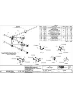
3 Figure 3, Valve and Manifold Assembly Figure 4, Pump Bottom View 2. (See Figure 12). 101. 140. Figure 5, Pump Front View (assembled). Repair Parts List for Figures 1 through 5. Item part Number Qty. description item part Number Qty. Description 2 DA12088167SR 1 Gasket (Includes item 156) 126 A109164 1 Compression Spring 3 DA1910900SR 1 Reservoir Assembly. Gal. 128 DA252028 1 Adjusting Screw DA4780900SR 1 Reservoir Assembly. Gal. 129 S1167 1 Gasket 10 DA3776006 2 Pin 130 CW306055 1 Lock Nut 14 DA15066 3 Lock Washer 131 CW307055 1 Cap Nut 15 B1018121 3 Hex Nut 132 B1009016 1 Ball ( in. dia.). 17 CW261225 6 Eyelet 133 C790010SR 1 Stem 18 F866028 6 Machine Screw 134 B1111203 1 O-Ring, Viton 19 CW259298 1 Baffle 135 B1111564 1 Washer 25 Contact Enerpac 1 Nameplate 137 B1086066 1 Lockwasher 26 DC818003 4 Pop Rivet 138 B1323028 1 Screw, Socket Head 27 DA608024 1 Vent Plug 139 DA544070SR 1 Handle 28 B1906503 1 O-Ring 140 R515245-2 1 Plug 36 DA931225 2 Insert 141 A1016245 1 Plug 101 DA12486840SR 1 Pump Manifold (includes # 121) 142 DA1011096 1 Elbow 102 CW179259 1 115 VAC Motor 143 DA261268 1 Tube DC1415259 1 220 VAC Motor (50 Hz) 144 CW467044 1 Retaining Ring 105 CW298950SR 1.
4 53 Piston Block Assembly 145 DA445107 2 Bearing 106 B1007503 1 O-Ring 146 B1007016 1 Ball 107 CW299950SR 1 .24 Piston Block Assembly 147 DA1564110 1 Spring 108 B1012803 1 O-Ring 148 DC433950 1 Plug Assembly 109 B1010028X 4 Screw 150 DA610900SR 1 Relief Valve Assembly 110 CW252107 1 Bearing 154 CU876028 3 Screw (10-24). 114 CW301228 1 Driven Gear 155 DA3585186 3 Spacer 115 B1097057 1 Spring Pin 156 See item 2 1 Gasket 116 CW199107 1 Bearing 190 DA12352290 1 Ball Seat 117 CW251107 1 Bearing 191 B1012565 2 Washer, Back-up 118 CW302107 1 Bearing 193 DC19503 1 O-Ring 119 CW303104 1 Shaft 195 DC866027 1 Lock Screw 121 DA5999900SR 1 Relief Valve (see Figure 4) 200 DC1947167 1 Gasket 123 DA12199290 1 Ball Seat Insert 124 B1004016 1 Ball ( in. dia.) Replacement Brushes for Electric Motor 125 DC990900 1 Ball Guide --- DA9655380 1 Brush Set for 115V Models Included in Repair Kit PUJ1200BK1 --- DA9656380 1 Brush Set for 220V Models 3.
5 Repair Parts List for Figure 6. * See page 9 for torque specifications and assembly notes. Item part Number Qty. Description 4 DA6954167 8 Gasket 19 5 DC2038028 8 Screw 6 E1100004 1 Thermostat, 115V. DC8401372 1 Thermostat, 220V. 7 C701222 2 Washer 24*. 8 M642028 2 Screw 21. 19 CW259298 1 Baffle 6. 21 DC7969960 2 Wire Assembly 24 DA11540380 1 Pin Housing 7, 8* 67 A1009245 2 Plug 67. 4, 5 *. Figure 6, Pump Top View 4. 44, 45. 3B 5 1. 2 4, 5, 43. 3A. 7. 3. 39. 3C. 4. 8. 101, 102. 107 103. 4, 5, 43. 290. 11. Figure 7, Shroud Wiring - Behind Motor Figure 8, Shroud Wiring - Front of Motor 16. 20. 4, 5, 43. 5. 3B. 38 6. 7. 3A 8. 3C. 105, 106. 104, 106. 48. Figure 9, Shroud Wiring - Left of Motor Figure 10, Shroud Wiring - Right of Motor 5. 41. 34 9. 48. Figure 11, Top View, Cord and Cables Repair Parts List for Figures 7 through 11.
6 Item part Number Qty. description item part Number Qty. Description 4 BC1310728 4 Screw (115V) 43 DA5974098 4 Screw Cover (115V). BC1310728 6 Screw (220V) DA5974098 6 Screw Cover (220V). 5 F75021 4 Lock Nut #6-32 (115V) 44 EHC3901075 3 Tie Down, Self Adhesive F75021 6 Lock Nut #6-32 (220V) 45 DA3131217 4 Cable Tie 9 DC7954960SR 1 Power Cord (115V) 48 DA3731009 2 Hole Plug DC10008960SR 1 Power Cord (220V) 101 DC8366380 1 Circuit Breaker (115V). 11 DA11539380 1 Receptacle DC8367380 1 Circuit Breaker (220V). 16 DC10035098 1 Shroud - PUM Models 102 DC8200380 1 Circuit Breaker Reset Cap DC10037098 1 Shroud - PUJ Models (115V) 103 DC8237023 1 Circuit Breaker Decal DC10036098 1 Shroud - PUJ Models (220V) 104 DC8371378 1 Secondary Fuse, 300mA. 20 E1500002 1 Switch 105 DC8370378 1 Primary Fuse, 62mA (115V).
7 34 CR759291 2 Cord Bushing DC8400378 1 Primary Fuse, 40mA (220V). 38 DA5875380 1 Transformer 106 DC8372378 2 Fuse Holder 39 E1300008 1 Relay, D1 - PUJ Only (115V) 107 DC7891026 1 Fuse Decal DC8280980 1 Relay, D1 - PUJ Only (220V) 290 DC8365380 1 EMI Filter (220V only). 41 DC7953900SR 1 Pendant Assy - PUJ Only Note: For replacement shroud assembly: Model PUM1200B only: Order Repair Kit DC7942900SR. PUJ Models, 115V: Order Repair Kit DC7933900SR. PUJ Models, 220V: Order Repair Kit DC7934900SR. 6. 2. 2 1. Switch Wiring Terminal #1 Black Terminal #2 Orange 1. 3. 4. Figure 12, Remote Pendant Assembly Repair Parts List for Figure 12. Item part Number Qty. description item part Number Qty. Description 1 CU598190 1 Pendant Body 3 DA1568007 1 Strain Relief 2 CU911372 1 Switch 4 DC10003960 1 Wire Assembly For complete replacement pendant assembly, order part number DC7953900SR.
8 7. CIRCUIT BREAKER. e1. 10 AMPS. NOTE: ALL WIRES ARE 18 AWG IN CROSS SECTION AREA. M1. 5 J1-1 J1-2 22. BR. 1 2. BLACK BLACK. 110 VAC J1-4 J1-3 S2 T MOM BLUE. BROWN S1 BR. OFF MOTOR AC. 1 4 MAN. BROWN. P1 THERMOSTAT. GRN/YEL BR. 22. BLUE. Figure 13, Electrical Schematic, PUM Models CIRCUIT BREAKER. e1 NOTE: ALL WIRES ARE 18 AWG IN CROSS SECTION AREA. 10 AMPS J1-1 J1-2. 5 22. BLACK BLACK BLUE. MOTOR AC. BR. 1 2. THERMOSTAT. J1-4 J1-3 S2 T (MOM). 110 VAC BROWN S1 4. (OFF). BR BR BR (MAN). BROWN. P1 6 BR. 1. GRN/YEL. d1. BLUE 6 6 4 5. 22. e2 BR BR. BLUE 62 mA. 22 7 BR. 7 GRAY S3. 41 41 8 32. 7 33 ORANGE 33. N. 22. 110 VAC. 24 VAC. BLACK EXTERNAL. 7. CONTROL. e3 STATION. P. 22. OR. 31 300 mA 32. BLUE 22. Figure 14, Electrical Schematic, PUJ Models (115V). 8. CIRCUIT BREAKER.
9 E1. 5 AMPS NOTE: ALL WIRES ARE 1mm SQ. IN CROSS BLACK M1 BLACK. SECTION AREA. J1-1 J1-2. BLUE. BR. F1 5 MOTOR AC. 1 2 EMI FILTER THERMOSTAT. BR BR 2 3 J1-4 J1-3 4 S2 T (MOM). 220 VAC S1. (OFF). BR BR BR BR (MAN). P1 GRN/YEL 6. LOAD. LINE. GRN/YEL. d1. BR 2. 6 6 BR. BLUE 21 22 BLUE 6. e2 4 5. 21. 40mA 41 33. 7 BR 8 7. GRAY. 7 N RELAY-SPDT. 41. 220 VAC. 8. S3 32. 24 VAC. RED OR 33. e3 BLACK. P EXTERNAL. 31 OR 32 CONTROL. BLUE 300 mA STATION. 22. m3. Figure 15, Electrical Schematic, PUJ Models (220V). Figure Item No. Torque Specification and/or Assembly Notes 1 18 Apply 1 drop Loctite #242 to threads. Torque to 12 to 18 in-lbs (1,4 to 2,0 Nm). 1 154 Torque to 27-31 in-lbs (3,1 to 3,5 Nm). 1 Note 1 Install bearing, Item 117, flush to " (2,54 mm) recessed from surface.
10 2 10 Trim wire length to 9 to 10 inches (228 - 254 mm) before attaching pins (item 10). Then insert into item 24. 2 15 Torque to 27 to 31 in-lbs, (3,1 to 3,5 Nm). 3 130,131 Torque to 15 to 20 ft-lbs (20 to 27 Nm). 3 138 Torque to 25-30 in-lbs (28,8 to 34,5 cm/kg). Apply Locite 242 to threads before assembly. 3 195 Torque to 6-10 ft-lbs (8,1 to 13,5 Nm). 4 15 Torque to 27-31 in-lbs (3,1 to 3,5 Nm). 4 109 Torque to 14 to 16 ft-lbs, dry (19,0 to 21,7 Nm). 4 121 Torque to 16-19 ft-lbs, dry (21,7 to 25,8 Nm). 4 143 Align tube to face mesh and splash lubricate upper needle bearing. 4 146 Seat must be coined prior to assembly. 4 148 Assemble with Loctite #545. 4 150 Relief valve setting should be from 250 to 400 psi (17,3 to 27,9 bar). 4 190 Assemble with Loctite #609. 4 Note 2 Stake threads after setting pressure.