Transcription of Repair Parts Sheet - Enerpac
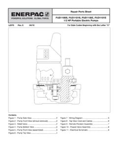
1 Repair Parts Sheet PUJ1200B, PUJ1200E, PUJ1201B, PUJ1201E, PUM1200B. 1/2 HP Portable Electric Pumps L2071 Rev. J 01/09 For Date Codes Beginning with the Letter F . T. Contents: Figure 1 - Pump Side View ..2 Figure 9 - Shroud Wiring-Left of Motor ..5. Figure 2 - Pump Front View (shroud removed)..2 Figure 10 - Shroud Wiring-Right of Motor ..5. Figure 3 - Valve and Manifold Assembly ..2 Figure 11 - Top View, Cord and Cables ..6. Figure 4 - Pump Bottom View ..2 Figure 12 - Remote Pendant Assembly ..7. Figure 5 - Pump Front View (assembled).
2 3 Figure 13 - Electrical Schematic, PUM Figure 6 - Pump Top View ..4 Figure 14 - Electrical Schematic, PUJ Models (115V) ..8. Figure 7 - Shroud Wiring-Behind Motor ..5 Figure 15 - Electrical Schematic, PUJ Models (220V) ..9. Figure 8 - Shroud Wiring-Front of Motor ..5. 26 See Heat Exchanger Figures Green Wire 25. 7 and 8. 14, 15*. Power Cord 1D 1C Green Wire 10*. 102. Solenoid Cables 154* Green Wires 155. 19. 17 141. 2, 156. 18*. 110. 200 140. 114. 117** 145. 119 115 3. 118 116. 27, 28. 145. 144. 36. * See page 9 for torque specifications and assembly notes.
3 * See page 9 for torque specifications and assembly notes. ** See Note 1 page 9. Insert must Figure 1, Pump Side View be flush Figure 2, Pump Front View (shroud removed). 131*. See Note 2, 129 page 9. 130*. 142. 129 150*. 128 105. 126 14, 15*. 109*. *See page 9 for torque specifications 125. 106. and assembly notes. 195* 143*. 124 190*. 101 191 146*. 106 109* 147. 123 148*. 193. 107 108. 191. 14, 15*. 132. 133 121*. 134. 135. 137. 138*. 139 *See page 9 for torque specifications and assembly notes. Figure 3, Valve and Manifold Assembly Figure 4, Pump Bottom View 2.
4 (See Figure 12). 101. 140. Figure 5, Pump Front View (assembled). Repair Parts List for Figures 1 through 5. Item part Number Qty. Description Item part Number Qty. Description 2 DA12088167SR 1 Gasket (Includes item 156) 126 A109164 1 Compression Spring 3 DA1910900SR 1 Reservoir Assembly. Gal. 128 DA252028 1 Adjusting Screw DA4780900SR 1 Reservoir Assembly. Gal. 129 S1167 1 Gasket 10 DA3776006 2 Pin 130 CW306055 1 Lock Nut 14 DA15066 3 Lock Washer 131 CW307055 1 Cap Nut 15 B1018121 3 Hex Nut 132 B1009016 1 Ball ( in. dia.)
5 17 CW261225 6 Eyelet 133 C790010SR 1 Stem 18 F866028 6 Machine Screw 134 B1111203 1 O-Ring, Viton 19 CW259298 1 Baffle 135 B1111564 1 Washer 25 Contact Enerpac 1 Nameplate 137 B1086066 1 Lockwasher 26 DC818003 4 Pop Rivet 138 B1323028 1 Screw, Socket Head 27 DA608024 1 Vent Plug 139 DA544070SR 1 Handle 28 B1906503 1 O-Ring 140 R515245-2 1 Plug 36 DA931225 2 Insert 141 A1016245 1 Plug 101 DA12486840SR 1 Pump Manifold (includes # 121) 142 DA1011096 1 Elbow 102 CW179259 1 115 VAC Motor 143 DA261268 1 Tube DC1415259 1 220 VAC Motor (50 Hz) 144 CW467044 1 Retaining Ring 105 CW298950SR 1.
6 53 Piston Block Assembly 145 DA445107 2 Bearing 106 B1007503 1 O-Ring 146 B1007016 1 Ball 107 CW299950SR 1 .24 Piston Block Assembly 147 DA1564110 1 Spring 108 B1012803 1 O-Ring 148 DC433950 1 Plug Assembly 109 B1010028X 4 Screw 150 DA610900SR 1 Relief Valve Assembly 110 CW252107 1 Bearing 154 CU876028 3 Screw (10-24). 114 CW301228 1 Driven Gear 155 DA3585186 3 Spacer 115 B1097057 1 Spring Pin 156 See item 2 1 Gasket 116 CW199107 1 Bearing 190 DA12352290 1 Ball Seat 117 CW251107 1 Bearing 191 B1012565 2 Washer, Back-up 118 CW302107 1 Bearing 193 DC19503 1 O-Ring 119 CW303104 1 Shaft 195 DC866027 1 Lock Screw 121 DA5999900SR 1 Relief Valve (see Figure 4) 200 DC1947167 1 Gasket 123 DA12199290 1 Ball Seat Insert 124 B1004016 1 Ball ( in.)
7 Dia.) Replacement Brushes for Electric Motor 125 DC990900 1 Ball Guide --- DA9655380 1 Brush Set for 115V Models Included in Repair Kit PUJ1200BK1 --- DA9656380 1 Brush Set for 220V Models 3. Repair Parts List for Figure 6. * See page 9 for torque specifications and assembly notes. Item part Number Qty. Description 4 DA6954167 8 Gasket 19 5 DC2038028 8 Screw 6 E1100004 1 Thermostat, 115V. DC8401372 1 Thermostat, 220V. 7 C701222 2 Washer 24*. 8 M642028 2 Screw 21. 19 CW259298 1 Baffle 6. 21 DC7969960 2 Wire Assembly 24 DA11540380 1 Pin Housing 7, 8* 67 A1009245 2 Plug 67.
8 4, 5 *. Figure 6, Pump Top View 4. 44, 45. 3B 5 1. 2 4, 5, 43. 3A. 7. 3. 39. 3C. 4. 8. 101, 102. 107 103. 4, 5, 43. 290. 11. Figure 7, Shroud Wiring - Behind Motor Figure 8, Shroud Wiring - Front of Motor 16. 20. 4, 5, 43. 5. 3B. 38 6. 7. 3A 8. 3C. 105, 106. 104, 106. 48. Figure 9, Shroud Wiring - Left of Motor Figure 10, Shroud Wiring - Right of Motor 5. 41. 34 9. 48. Figure 11, Top View, Cord and Cables Repair Parts List for Figures 7 through 11. Item part Number Qty. Description Item part Number Qty. Description 4 BC1310728 4 Screw (115V) 43 DA5974098 4 Screw Cover (115V).
9 BC1310728 6 Screw (220V) DA5974098 6 Screw Cover (220V). 5 F75021 4 Lock Nut #6-32 (115V) 44 EHC3901075 3 Tie Down, Self Adhesive F75021 6 Lock Nut #6-32 (220V) 45 DA3131217 4 Cable Tie 9 DC7954960SR 1 Power Cord (115V) 48 DA3731009 2 Hole Plug DC10008960SR 1 Power Cord (220V) 101 DC8366380 1 Circuit Breaker (115V). 11 DA11539380 1 Receptacle DC8367380 1 Circuit Breaker (220V). 16 DC10035098 1 Shroud - PUM Models 102 DC8200380 1 Circuit Breaker Reset Cap DC10037098 1 Shroud - PUJ Models (115V) 103 DC8237023 1 Circuit Breaker Decal DC10036098 1 Shroud - PUJ Models (220V) 104 DC8371378 1 Secondary Fuse, 300mA.
10 20 E1500002 1 Switch 105 DC8370378 1 Primary Fuse, 62mA (115V). 34 CR759291 2 Cord Bushing DC8400378 1 Primary Fuse, 40mA (220V). 38 DA5875380 1 Transformer 106 DC8372378 2 Fuse Holder 39 E1300008 1 Relay, D1 - PUJ Only (115V) 107 DC7891026 1 Fuse Decal DC8280980 1 Relay, D1 - PUJ Only (220V) 290 DC8365380 1 EMI Filter (220V only). 41 DC7953900SR 1 Pendant Assy - PUJ Only Note: For replacement shroud assembly: Model PUM1200B only: Order Repair Kit DC7942900SR. PUJ Models, 115V: Order Repair Kit DC7933900SR. PUJ Models, 220V: Order Repair Kit DC7934900SR.