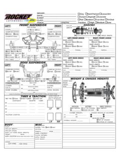
Transcription of REQUIRED READING - Custom Works R/C
1 REQUIRED READINGT hank You and Congratulations on purchasing this Aggressor! Within this kit you will find arace winning car with over 17 years worth of Custom Works design and quality. In orderfor you to realize this race car s winning potential it is important to follow the written textalong with the pictures included. The steps REQUIRED to build this car are very easy, as longas you read before you instructional format for building this car is to open each bag in alphabeticalorder. Each bag of parts will be broken down into Steps in the manual. All partsand hardware needed to complete all steps for each separate bag, will be found ineach individual bag.
2 There is no need to steal screws from other bags. In the rareevent you need to look in a different bag for a certain part, it will be noted hardware (screws, washers, nuts, ) are referred to by size and type in theinstructions. To help clarify which screw or nut the instruction is calling for refer to theHARDWARE REFERENCE supplement. The size of the screw or nut should match the shadow of the same piece very ID s are: FH=Flat Head BH=Button Head SH=Socket Head SS=Set ScrewDo NOT use power screwdrivers to drive screws into parts. The fast rotation speed can easilymelt and strip plastic parts or cross-thread into the aluminum TOOLSD ouble Sided " Drill BitSuper GlueHobby ScissorsX-Acto Knife220 Grit SandpaperSmall Needle Nose PliersPhillips Head Screw Driver400 Grit Sandpaper3/16" WrenchBlue Loctite#43 Drill BitBag AChassisTo begin building this kit locate the bag of graphite parts, start by lightly sanding theedges of the graphite pieces using a medium grade sandpaper like 220 Grit or asanding drum on a Dremel.
3 Run a thin bead of Super Glue around the edges to givepieces greater durability and reduce the chance of splitting the chassis in a hardwreck. To smooth the edges of the battery slots you may use a file or an appropriatepointed sanding stone on a #1: Attach the #8010 Front Bumper to the #8000 Chassis using (2) 3/8" FH Screws thru the bottom of theChassis with (2) #5212 Washers and (2) 4-40 Lock-nuts asshown in Figure # #2: Attach each #8071 Front Track Plates to themain chassis using (1) 3/8" FH Screw thru the bottom ofthe Chassis and (1) 4-40 Lock-nut. Notice that the screwpasses thru the Chassis in the 3rd hole from the top ofthe Chassis in the row of holes and then thru the 2ndhole from the top of the 5 holes on the Front Track Plateas shown in Figure # #3: Using (2) 1/2" BH Screws mount (1) #8018 Center ShockTower on each side of the #8023 Center Shock Anchor and fasten with(2) 4-40 Lock-nuts.
4 Notice the antenna mount hole in the Anchor andthe holes in the Shock Tower face away from each other. Mount theCenter Shock Tower to the Chassis with (2) 3/8" FH Screws thru theholes shown in Figure # #4: Mount the (2) #8022 Anchor Plates to the Chassisusing (4)1/4" FH Screws as shown in Figure # #5: Attach the #8012 Shock Tower to the Anchor Platesusing (2) 1/4" BH Screws. Notice that side with the furthestdistance between the shockmounting holes and the shock towermounting holes is on the left side ofthe car as shown in Figure #5. Nowmount (2) #8121 Ball Studs thru thetop most holes in the shock towerand the balls facing the front of thecar using (2) 4-40 BStep #6: Mount (2) #8013 Body Mounts to the tops of theAnchor Plates using (4) 1/4" BH Screws thru the holes asshown in Figure # #7: Attach the #8011 Side Bumper to the chassisusing (2) 3/8" FH Screws thru the bottom of the Chassiswith (2) 5212 Washers and (2) 4-40 Lock-nuts as shown in Figure#7.
5 You may tighten these downso the bumper does not move oryou may just barely snug thescrews so that the bumper will give if you were to bumpthe PodStep #1: Attach the #8021 Left Pod Plate and the #8020 Motor PodPlate to the #8016 Bottom Plate with (4) 1/4" FH Screws as shown in Figure #8. Notice thatthe back edge of the bottom plate is directly underneath the oval holes for the bearingcarriers, at this point in time we are building the car with a standard length #2: Mount (2) #8120 Tall Ball Studs and (1) #8121 Ball Studto the #8014 Shock Plate thru the holes shown in Figure #9 using(3) 4-40 Lock-nuts. Then mount the Shock Plate to the #8015 TopPlate using (2) 3/8" FH Screws and (2) 4-40 Lock-nuts thru theRIGHT most holes in the Top Plate also #3: Attach the Top Plate to thePod Plates using (4) 1/4" FH Screwsthru the FORWARD most screws onthe Top Plate.
6 Your rear pod should look like that in Figure # #4: Place (2) 3/8" FHScrews thru the LEFT most setof each pair of holes on the front on the Bottom Plate asshown in Figure #11. Press (1) #8049 T-Bar Spacers overeach screw and now place the #8060 .063" CenteredFiberglass T-Bar over the two screws and secure with (2)4-40 CRear AxleStep #5: Finish mounting the T-Bar to the Rear Pod by mounting the#8017 Rear Steer Clip to the Bottom Plate with (2) 1/4" FH Screwsand (2) 4-40 Lock-nuts. The Clip should be mounted under the T-Barand on top of the Bottom Plate. Fasten the Clip to the T-Bar with (1)1/4" BH Screw and (1) 4-40 Lock-Nut as shown in Figure # : The Rear Steer Clip has a notch on one end, this is the endused to angle the pod 1/2 Degree.
7 The opposite end without thenotch is the 0 Degree side. To run the pod in the offset position, just flip the rearsteer clip over using the same end either with or without the #6: Following the assembly shown in Figure#13, mount the #8047 Pivot Ball Carriers and #8048 Pivot Balls to the T-Bar using (4) 3/8" 2-56 X 3/8" BHScrews per Carrier. Just snug the Screws to thecarrier, the Pivot Balls should move very freely in #7: Finally mount the T-Bar and Rear Podassembly to the Chassis using (2) 5/8" FHScrews thru the Chassis and secure with (2) 4-40 Lock-Nuts. Your car should now look like the oneshown in Figure # #1: Press (12) 1/8" Balls into the #4600 Spur Gear and (1) #1232 1/4" X 3/8"Unflanged Bearing to the center of the Gear.
8 Place (1) #8035 D-Drive Diff Ring ontothe #8030 Axle so that the notch on the Axle and Ring line up. Apply a small amountof #4201 Blue Goo Grease to one side of the Diff Ring andon both sides of the Balls in the Spur Gear. Slide the gearonto the axle and apply a small amount of Grease to theother Diff Ring and slide it onto the axle as well with thegreased side facing the Spur Gear. Use Figure #15 as DSide ShocksStep #2: Following Figure #16, press (1) #12311/4" X 3/8" Flanged Bearing into each end of the#8031 Standard Diff Hub. Slide the Hub onto the axleand align the notch in the Hub into the Diff Ring. Nextplace (1) #8034 Diff Thrust Cone onto the axle withthe taper facing the Hub.
9 Then slide (3) #8034 BellWashers onto the axle with the taper pointing awayfrom the Thrust Cone. Secure the Diff Assembly to theAxle using (1) #8036 8-32 Nylon : Do NOT overtighten the Diff Nut, just tighten it a half turn past when it istight to the Bell Washers. You will adjust the Diff Nut tighter oncethe car is being #3: Press (1) #1231 1/4" X 3/8" Flanged Bearing into eachRide Height Adjuster with the 3 Dots on it. Place (1) #8040 RideHeight Adjuster into each oval on the rear pod plates as shown inFigure # : There are 4 different Ride Height Adjuster in the kitmarked by a number on the bottom of the part.
10 Never mix andmatch different sized Ride Height Adjusters, the axle should always slide thru bothbearings #4: Slide the Axle thru the Bearings in the Ride Height Adjusters mounted inthe Rear Pod Plates. Following Figure # 18, slide (1) #8037 .050" Axle Spacer and(2) #8038 .100" Axle Spacers onto the axle with the tapered end facing toward theSpur Gear. Finally place the #8033 ClampingHub onto the axle and tighten so the screw isjust snug, over-tightening will just bend orbreak the hub. There should be just a paperwidth of play when the axle slides side : Left over in the bag is (8) 3/8" SH screws to be used to mount the RearTires to the Axle the following 7 steps, complete each step twice to make 2 #1: As shown in Figure #19, soak the #8103 VC foam with 20wtShock Oil and push it into the VC ShockBag EStep#2: Fill the #8101 Shock Body with 30 weight shock oil up to the lineshown in Figure #20 and insert the #8102 Shock Piston all the way till itbottoms #3.