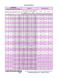
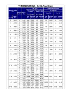
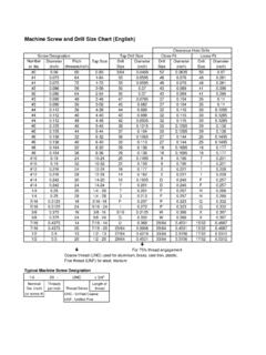
Transcription of Requirements for the Attachment of Communication Cable …
1 Overhead Distribution General Information Utility Reference Specification Attachment of Communication Company Facilities on PPL Company Poles 6-01-140 0000-000-ST-6001 Custom ID: DCS 6-01 Revision: 12 Effective Date: 05/04/2020 Page 120 of 174 2020 PPL Electric Utilities Corporation. All rights reserved. 6-01-140 Utility Reference Specification Attachment of Communication Cable Facilities on PPL Poles Requirements for the Attachment of Communication Cable Facilities on PPL Poles Replaces: URS-3002 URS-3004 URS-101C-304 A-157649 Overhead Distribution General Information Utility Reference Specification Attachment of Communication Company Facilities on PPL Company Poles 6-01-140 0000-000-ST-6001 Custom ID: DCS 6-01 Revision: 12 Effective Date: 05/04/2020 Page 121 of 174 2020 PPL Electric Utilities Corporation.
2 All rights reserved. Reference Notes for Drawings: General 1. The term Communication Cable facility refers to facilities installed by telephone, CATV, telecommunication, and public/private companies for voice, video, or data transmission. The owner of the Communication Cable facilities must follow the proper Attachment permit procedures as specified by the appropriate Attachment agreement. Please reference PPL Specification 6-01-160 for wireless antenna installations. 2. Any rearrangement of PPL electrical facilities or other Communication facilities necessary to accommodate the Attachment of Communication Cable facilities on PPL poles must be negotiated by the Communication Cable facility owner with the existing facility owner and completed prior to making the Attachment .
3 3. All new Communication cables and cabinets shall be marked at each pole in a manner such that the ownership of the facility can be determined by PPL personnel from ground level. Existing Communication cables and cabinets should be marked when maintenance is performed on that facility. 4. Bolt ends must not project more than one inch beyond the nut. Cable Attachments 5. The Communication Cable must be attached directly to the pole surface or attached using metallic or fiberglass offset brackets. Offset brackets should only be used to provide the required horizontal clearance to buildings, signs, trees, and similar facilities or to reduce the change in direction (angle) of the Communication Cable .
4 Offset brackets should not be used to avoid required vertical clearances. Drilled holes in a wood pole shall be spaced a minimum of 4 inches vertically when they are parallel (in the same direction) through the pole. Drilled holes that are perpendicular (90 degrees apart) through the pole shall be spaced a minimum of 2 inches vertically. Attachment to metal distribution poles must be clamped or banded to the poles with stainless steel straps. The drilling of holes in a metal pole for a bolt Attachment is prohibited unless the applicant first obtains written authorization due to a highly unusual circumstance.
5 All attachments to metal poles require prior approval of PPL engineering personnel. Attachment to fiberglass poles should be treated like attachments to wood poles with the following exceptions: a) Attachment to fiberglass poles must be made using through bolts for the hardware. b) Lag screws are not permitted in fiberglass poles. Overhead Distribution General Information Utility Reference Specification Attachment of Communication Company Facilities on PPL Company Poles 6-01-140 0000-000-ST-6001 Custom ID: DCS 6-01 Revision: 12 Effective Date: 05/04/2020 Page 122 of 174 2020 PPL Electric Utilities Corporation.
6 All rights reserved. c) DO NOT drill the Attachment hole at the same height as the pre-drilled climbing holes are located. d) The Attachment holes should have a minimum distance of 2 inches vertically from the pre-drilled holes. e) DO NOT drill holes where the distance of the edge of that hole would be within 2 inches from the edge of any existing hole. 6. The use of wood arms for any Communication Cable attachments is not permitted for new installations, except with the prior written approval of PPL engineering personnel for each specific Attachment location.
7 7. Service Drop a single wired drop installed to provide communications service to an individual customer, starting at the customer s premises and extending to the closest available utility pole, without requiring any additional anchors or guying to comply with all applicable engineering standards. A Communication service drop may attach in-span or directly to a single pole. When attaching a Communication service drop Cable to a pole, it must be submitted in the Application Portal to ensure compliance with this definition and to ensure that the Communication service drop is accounted for as an Attachment .
8 A Communication service drop may extend more than one pole, upon review and approval by PPL, when the following conditions are met: a) where it is necessary to maintain code required ground or roadway clearance, a second pole may be used to provide support for the single Communication service drop Cable ; or b) on private property when all the following conditions are met: i) it is a single wired drop; ii) submitted in the Application Portal; iii) all poles associated with the service drop are on a single private property; and iv) the Communication service drop is no more than 500 in length measured from the customer s premises Clearance Requirements 8.
9 Clearance between PPL electrical facilities and Communication Cable facilities must be in accordance with the latest edition of the National Electrical Safety Code (NESC). Use Section 23 of the NESC to determine the clearances required at the pole and in-span. It specifies that the required vertical clearances must be measured surface-to-surface, not center-to-center. Diagonal measurements do not apply to electrical clearances. Additional vertical clearance may be needed on the pole to achieve the required in-span clearances. Communication reinforcing straps should be considered when measuring vertical clearances between Communication facilities and electrical facilities.
10 Overhead Distribution General Information Utility Reference Specification Attachment of Communication Company Facilities on PPL Company Poles 6-01-140 0000-000-ST-6001 Custom ID: DCS 6-01 Revision: 12 Effective Date: 05/04/2020 Page 123 of 174 2020 PPL Electric Utilities Corporation. All rights reserved. 9. The in-span vertical clearance as specified by the NESC in Rule 235 between the lowest electrical conductor and the highest Communication Cable is 30 inches based on the following conditions: a) The upper conductor is at final sag at 120 F or the maximum conductor operating temperature and the lower conductor is at final sag at the same ambient conditions as the upper conductor without electrical loading, or b) The upper conductor is at final sag at 32 F with a 1/2 inch radial ice thickness and the lower conductor is at final sag at the same ambient conditions as the upper conductor without electrical loading and without ice.